Panhard crankshaft truing
Sunday 04 November 2012 Filed in: Blog Comments
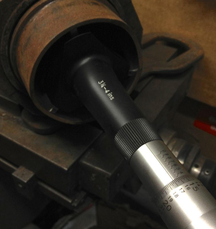
Too cold to work in the roof of the house first thing in the morning today, so for a few hours while it got warmer, I decided to make my crankshaft truing tool on the Elliot mill. I can’t do anything else until I collect the other liners and crankshafts, so it seemed fair to make a start on something else.
Several months ago, Martin McClarence had given me an ex Woody crankshaft to true up that had turned somehow.
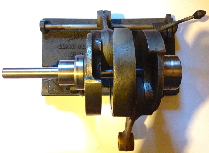
When he installed this low mileage crankshaft (10 miles) into his engine, it decided to let go a little and break the piston ring seal and damage the timing gear cover. I knew it was bent because Martin couldn’t fit the rear bearing plate in the crankcase, when the crankshaft was installed in the front bearing, and this was confirmed by the wobble I saw on the Alpha crank truing rig. It is very awkward to true one of these cranks on a traditional crankshaft rig, which is why making the special tool is so beneficial.
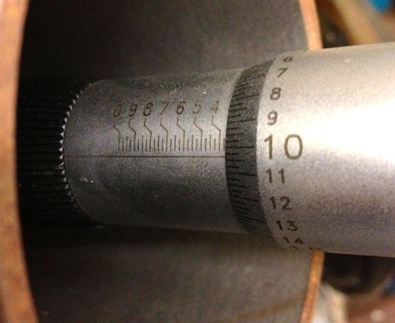
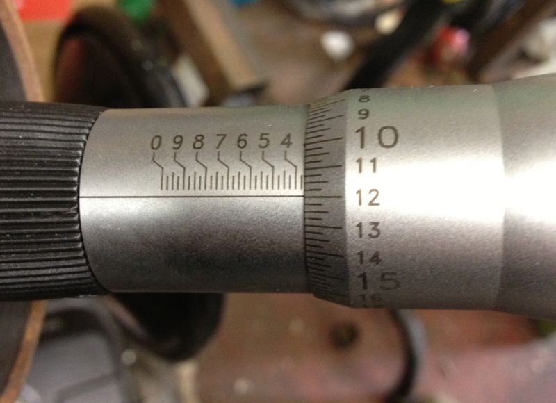
After making my crankshaft tool, I decided to test it out on Martin’s crankshaft, and pleasingly it went down the middle until it hit the rear crankshaft web. A quick close up snap will show the tool and crankshaft hole are not concentric.
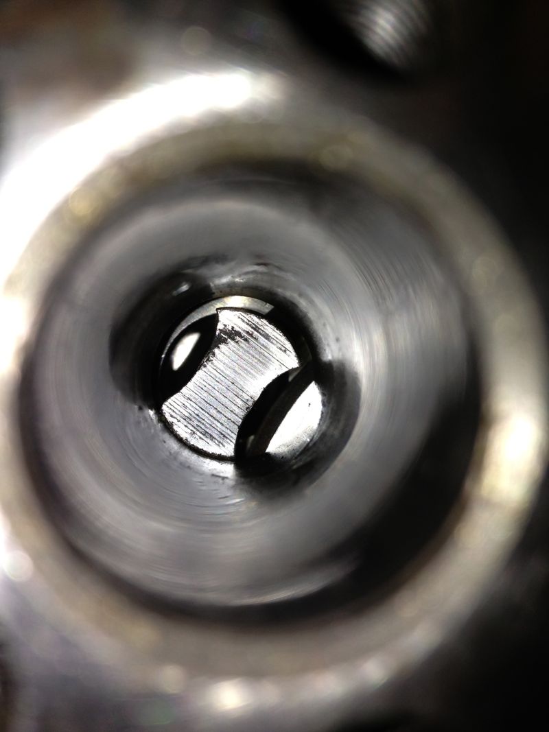
However, after looking at the crankshaft, a good swipe with a brand new #4 Thor from a decent height might suffice to put things right. It had to be bigger than my old crank bashing hammer, as these crankshafts have quite large pins, compared to the motorcycle crankshafts I have messed with in the past..Thor in right hand, crank in left, a couple of big swings and a few big hits later, and this is the result.
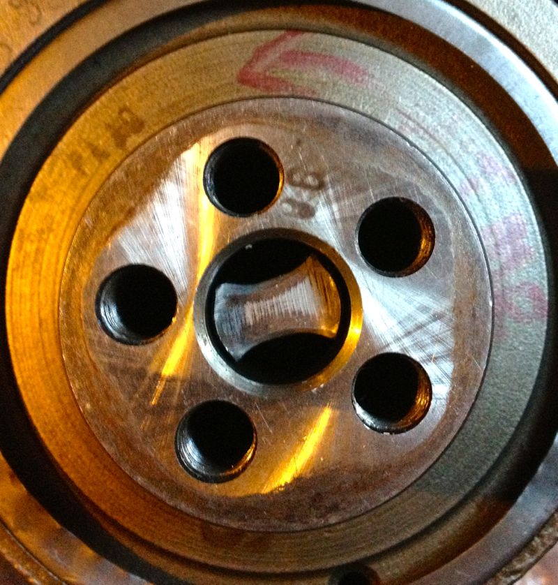
A quick check on the Alpha crankshaft truing rig, and it gets the all clear.
Now the question is do I leave it be, do i pin it or do I weld it with a pencil torch and TID set? I’ll let Martin make the decision.
UPDATE
He has and he’d like it pinning, so the saga continues...
Several months ago, Martin McClarence had given me an ex Woody crankshaft to true up that had turned somehow.
When he installed this low mileage crankshaft (10 miles) into his engine, it decided to let go a little and break the piston ring seal and damage the timing gear cover. I knew it was bent because Martin couldn’t fit the rear bearing plate in the crankcase, when the crankshaft was installed in the front bearing, and this was confirmed by the wobble I saw on the Alpha crank truing rig. It is very awkward to true one of these cranks on a traditional crankshaft rig, which is why making the special tool is so beneficial.
After making my crankshaft tool, I decided to test it out on Martin’s crankshaft, and pleasingly it went down the middle until it hit the rear crankshaft web. A quick close up snap will show the tool and crankshaft hole are not concentric.
However, after looking at the crankshaft, a good swipe with a brand new #4 Thor from a decent height might suffice to put things right. It had to be bigger than my old crank bashing hammer, as these crankshafts have quite large pins, compared to the motorcycle crankshafts I have messed with in the past..Thor in right hand, crank in left, a couple of big swings and a few big hits later, and this is the result.
A quick check on the Alpha crankshaft truing rig, and it gets the all clear.
Now the question is do I leave it be, do i pin it or do I weld it with a pencil torch and TID set? I’ll let Martin make the decision.
UPDATE
He has and he’d like it pinning, so the saga continues...
Comments
Panhard bare cylinder isn't tapered (updated)
Friday 02 November 2012 Filed in: Blog Comments
I have long said that boring a tapered liner is extremely difficult, and I often wondered how Panhard did it, but today I found out for sure.
I have measured the internal diameters of a bare aluminium cylinder casting, and it is truly parallel internally. I have also measured a new old stock liner and this was parallel internally and externally, so it was suggested by me, that Panhard machined a tapered liner was the stuff of legends or folklore.
I actually surprised myself by accidentally stumbling upon a method of boring a tapered liner the other day, and although I might still do this using the boring bar directly, I didn’t think this is what Panhard did, as it’s not really a production method. So how else could this be achieved?
It was possible that Panhard used a tapered honing process, but again it’s way too slow and therefore probably not what Panhard did either.
I knew the cylinder finning and casting were tapered, and I wondered whether this fact was lost in translation when the cylinder was being described in the press releases, but then I had my eureka moment and I discovered an even easier way. I was drawing up a new cylinder in CAD looking at the original casting, and taking measurements, when it hit me.
The answer lies in the liner or sleeve is an interference fit in the cylinder casting, and depending on the interference, the strength of the cylinder casting (thickness of the walls) this determines how much the liner distorts, this distortion is what tapers the cylinder bore.
When the bare cylinder is warmed up the interference fit is lost, and the cold liner or sleeve is “dropped” in place, but when it cools the cylinder starts to squeeze the liner. However the cylinder walls have different thicknesses tapering from the bottom of the liner to the top, as in the picture below.
What this means is for a given interference fit along its length, the liner will be squeezed more at the top than the bottom, because the cylinder is much stiffer in compression at the top, and less stiff as the liner moves away from the top. The reality is on a cold bore today when it was 4ºC, the diameters measured across the liner from top to bottom are as shown.
3.3604” at the very top (closest to the combustion chamber in the above photo)
3.3620” in the middle of the liner, measured roughly in the middle of the cylinder casting.

3.3626” in the liner, measured at the base of the cylinder casting.
Lastly, at the base of the liner skirt, which is the bit that isn’t contained by the cylinder casting, that is where the spigot goes into the crankcase, the actual machined bore diameter of 3.3670” is seen again on the micrometer.
There is a 0.007” variation on a cold cylinder from top to bottom, and no wonder people often said some engines were quiet and slow running, until they warmed up slightly!
The mystery as to how the cylinder bore becomes tapered is finally solved for me at least, and possibly a few others too.
It also means you can parallel bore the cylinder casting or sleeve, and you will not destroy the factory taper, but you must always take the liner or sleeve out of the cylinder casting otherwise you will.
If you make a larger bore engine using the standard cylinder casting & original interference fit, you will reduce the taper effect at the top, because you have reduced the wall thickness and compressive stiffness pro rata.
I am almost ready to machine the cylinders to suit the new pistons, but I need to explore a couple of other things first, namely how perpendicular is the bore, and how does the cylinder bore change with temperature versus the piston crown & ring body, which will establish the actual bore size required for the liner or sleeve.
UPDATE Saturday 3 November 2012
It seems that at about a cylinder temperature of 120ºC the bore is truly parallel, and approximately 0.007” larger at the combustion chamber end of the liner, than when it is cold.
I have measured the internal diameters of a bare aluminium cylinder casting, and it is truly parallel internally. I have also measured a new old stock liner and this was parallel internally and externally, so it was suggested by me, that Panhard machined a tapered liner was the stuff of legends or folklore.
I actually surprised myself by accidentally stumbling upon a method of boring a tapered liner the other day, and although I might still do this using the boring bar directly, I didn’t think this is what Panhard did, as it’s not really a production method. So how else could this be achieved?
It was possible that Panhard used a tapered honing process, but again it’s way too slow and therefore probably not what Panhard did either.
I knew the cylinder finning and casting were tapered, and I wondered whether this fact was lost in translation when the cylinder was being described in the press releases, but then I had my eureka moment and I discovered an even easier way. I was drawing up a new cylinder in CAD looking at the original casting, and taking measurements, when it hit me.
The answer lies in the liner or sleeve is an interference fit in the cylinder casting, and depending on the interference, the strength of the cylinder casting (thickness of the walls) this determines how much the liner distorts, this distortion is what tapers the cylinder bore.
When the bare cylinder is warmed up the interference fit is lost, and the cold liner or sleeve is “dropped” in place, but when it cools the cylinder starts to squeeze the liner. However the cylinder walls have different thicknesses tapering from the bottom of the liner to the top, as in the picture below.
What this means is for a given interference fit along its length, the liner will be squeezed more at the top than the bottom, because the cylinder is much stiffer in compression at the top, and less stiff as the liner moves away from the top. The reality is on a cold bore today when it was 4ºC, the diameters measured across the liner from top to bottom are as shown.
3.3604” at the very top (closest to the combustion chamber in the above photo)
3.3620” in the middle of the liner, measured roughly in the middle of the cylinder casting.
3.3626” in the liner, measured at the base of the cylinder casting.
Lastly, at the base of the liner skirt, which is the bit that isn’t contained by the cylinder casting, that is where the spigot goes into the crankcase, the actual machined bore diameter of 3.3670” is seen again on the micrometer.
There is a 0.007” variation on a cold cylinder from top to bottom, and no wonder people often said some engines were quiet and slow running, until they warmed up slightly!
The mystery as to how the cylinder bore becomes tapered is finally solved for me at least, and possibly a few others too.
It also means you can parallel bore the cylinder casting or sleeve, and you will not destroy the factory taper, but you must always take the liner or sleeve out of the cylinder casting otherwise you will.
If you make a larger bore engine using the standard cylinder casting & original interference fit, you will reduce the taper effect at the top, because you have reduced the wall thickness and compressive stiffness pro rata.
I am almost ready to machine the cylinders to suit the new pistons, but I need to explore a couple of other things first, namely how perpendicular is the bore, and how does the cylinder bore change with temperature versus the piston crown & ring body, which will establish the actual bore size required for the liner or sleeve.
UPDATE Saturday 3 November 2012
It seems that at about a cylinder temperature of 120ºC the bore is truly parallel, and approximately 0.007” larger at the combustion chamber end of the liner, than when it is cold.
Panhard bare cylinder isn't tapered
Saturday 15 September 2012 Filed in: Blog Comments
Panhard liners have had tapered bores since the early days. However when it’s time to rebuild them, I never found this out.
It was assumed by others, and I had no reason to question whether the liner was tapered internally, or perhaps the aluminium cylinder itself? The reasoning behind this was, if the aluminium cylinder was slightly narrower at the combustion chamber end, it would squeeze the sleeve and so make it tapered.
Yesterday, I got a Tesa three point bore micrometer in the post, and I was finally able to measure the internal bore of the aluminium cylinder.
I measured the bottom, middle and top of the bore of the bare aluminium cylinder, that’s without a liner or sleeve being fitted.
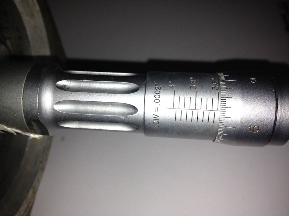
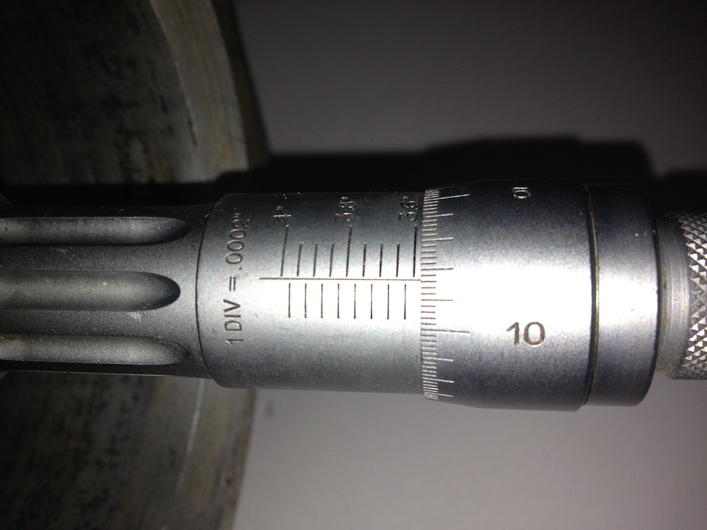
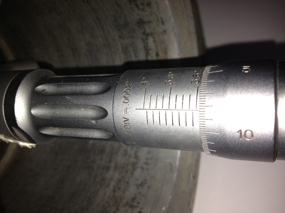
The divisions of the micrometer are 0.0002” or 2/10ths of a thou. There is no taper on the bare cylinder, so thats’s another bit of folklore or legend out of the way, and the only other way to achieve this would be to make the internal sleeve or cast iron liner taper outwards at the top, so that when it is inserted in the heated cylinder, upon cooling it compresses slightly more at the top than the bottom. Next up is to measure a few sleeves or liners and check whether this was done.
Interestingly the days of tapered bores were numbered with improvements in aluminium piston alloys and better machining, and Panhards have bigger issues with their piston design, so obsessing about having a tapered bore is rather irrelevant and futile.
UPDATE 23 September 2012
I measured the matching sleeve, taken from the aluminium cylinder above, and the external diameters are truly parallel, so I now know I will not have any issues when I bore the cylinder liner or sleeve.
It was assumed by others, and I had no reason to question whether the liner was tapered internally, or perhaps the aluminium cylinder itself? The reasoning behind this was, if the aluminium cylinder was slightly narrower at the combustion chamber end, it would squeeze the sleeve and so make it tapered.
Yesterday, I got a Tesa three point bore micrometer in the post, and I was finally able to measure the internal bore of the aluminium cylinder.
I measured the bottom, middle and top of the bore of the bare aluminium cylinder, that’s without a liner or sleeve being fitted.
The divisions of the micrometer are 0.0002” or 2/10ths of a thou. There is no taper on the bare cylinder, so thats’s another bit of folklore or legend out of the way, and the only other way to achieve this would be to make the internal sleeve or cast iron liner taper outwards at the top, so that when it is inserted in the heated cylinder, upon cooling it compresses slightly more at the top than the bottom. Next up is to measure a few sleeves or liners and check whether this was done.
Interestingly the days of tapered bores were numbered with improvements in aluminium piston alloys and better machining, and Panhards have bigger issues with their piston design, so obsessing about having a tapered bore is rather irrelevant and futile.
UPDATE 23 September 2012
I measured the matching sleeve, taken from the aluminium cylinder above, and the external diameters are truly parallel, so I now know I will not have any issues when I bore the cylinder liner or sleeve.
Panhard Engine Dyno Curves
Friday 24 August 2012 Filed in: Panhard Dyno
I had a nice telephone conversation the other day with a Belgian guy, who has forwarded on a few dyno curves from his engines and the Don Racine Panhard engined Aardvark special.
i have posted them here as a reference. I will add a few comments later, but for this Gawski tuned example, the upper curve is the Fuel/Air ratio, whereas the bottom three, are Engine Torque (calculated), Engine Horsepower(calculated), and Front Wheel Horsepower respectively.
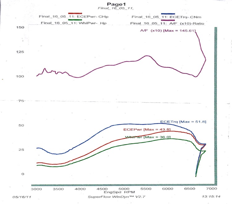
A standard MEP with a single Zenith NDIX carburettor, possibly a standard Tigre set up?
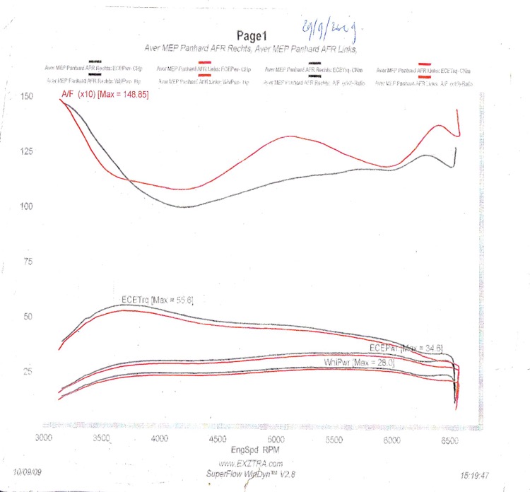
The Don Racine Aardvark example
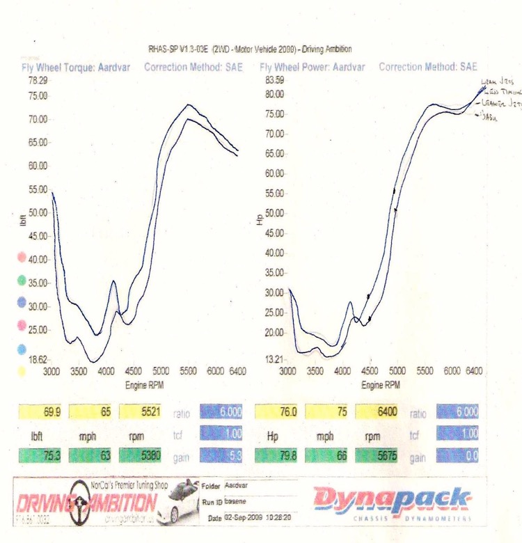
The horsepower numbers do not really matter unless they are on the same dyno, but the shape of the Torque curves is interesting.
i have posted them here as a reference. I will add a few comments later, but for this Gawski tuned example, the upper curve is the Fuel/Air ratio, whereas the bottom three, are Engine Torque (calculated), Engine Horsepower(calculated), and Front Wheel Horsepower respectively.
A standard MEP with a single Zenith NDIX carburettor, possibly a standard Tigre set up?
The Don Racine Aardvark example
The horsepower numbers do not really matter unless they are on the same dyno, but the shape of the Torque curves is interesting.
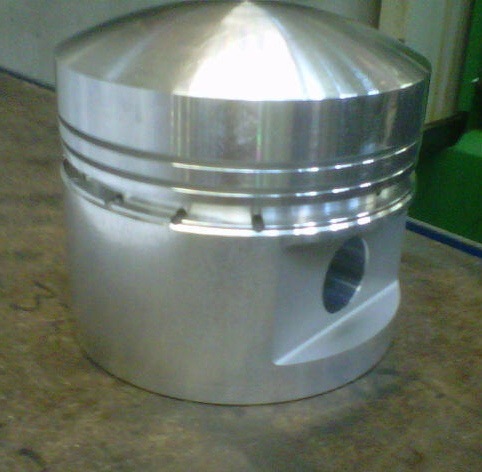
Panhard piston first batch delivered
Thursday 19 July 2012 Filed in: Panhard Piston
The pistons were delivered the other day, and here is the first picture of the bare piston, and below this another with the old piston for reference.
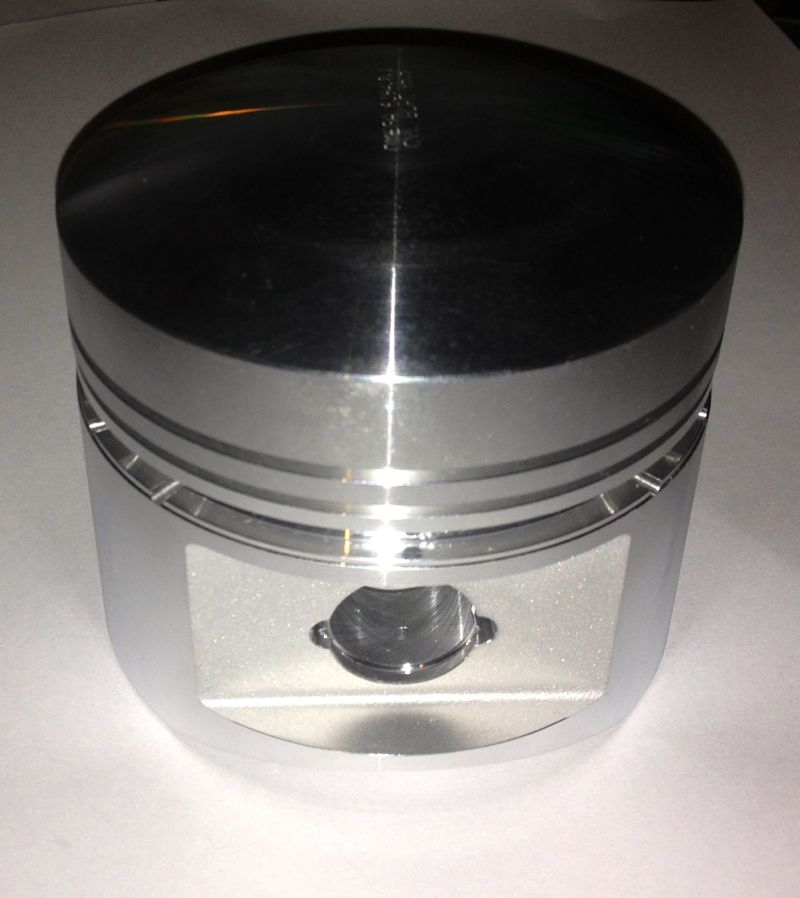
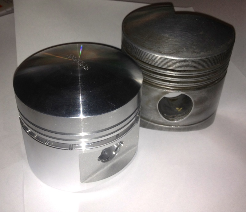
More pictures to follow, once I get back from my bike trip.
More pictures to follow, once I get back from my bike trip.
Panhard front pulley kit
Sunday 08 July 2012 Filed in: Panhard Parts
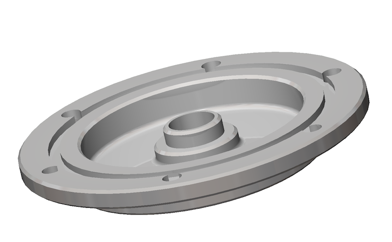
I sent a few links off to a few people and from their feedback and just to avoid any confusion, the new front pulley kit will only work with a revised seal arrangement. To update the seal you need to fit these components, which will be available assembled or as separate parts for future maintenance if required.
However, as the space available is limited within the OEM timing gear cover, the front pulley kit and the seal kit are designed to be an easy fit upgrade option, which is much the same philosophy as the filter kit upgrades, and an added bonus for those that are not removing the engine or doing additional works in this area. Initially fitting this kit might seem daunting at first, but it is really designed to be as foolproof as possible.
Obviously when the parts are made, I will post a video outlining the installations and use in situ photographs covering the assembly procedure.
ASSEMBLY PROCEDURE
First remove the old pulley after removing the fan and saving all the springs and wooden blocks. Leaving the timing gear cover in place, install the inner part of the pulley, which will consist of an aluminium centre and a steel inner ring already assembled together, engaging the key in the slot.
Next place the lightly oiled seal assembly, which will come ready assembled, over the timing gear front pulley aperture, and slide the seal over the inner ring until the steel ring is against the timing gear cover. The stainless steel ring should just be inside the opening, and now needs pressing into place.
Using the crankshaft front pulley bolt, and a spacer, press the seal assembly into position, by tightening the crankshaft bolt until the stainless steel seal adaptor is fully seated against the timing gear cover. The interference fit should be enough of an oil tight arrangement, but there is an O ring seal detail to make sure it is.
Remove the front pulley crankshaft bolt & spacer, and then place remaining part of the front pulley kit, which will be a sliding fit, into the steel inner ring. Next fit all the springs, wooden blocks, and other fan related parts and rebuild the fan assembly, not forgetting the V belt. Then refit the crankshaft pulley bolt and tighten to OEM torque figures.
Note, there is a dowel pin detail that aligns the front pulley in a set position, which will be used for those owners that want to fit a trigger wheel, whose primary purpose is to facilitate the use of third party ignition or modern engine management systems to their vehicle.
Panhard crankshaft pulley with trigger wheel (updated)
Friday 06 July 2012 Filed in: Panhard Parts
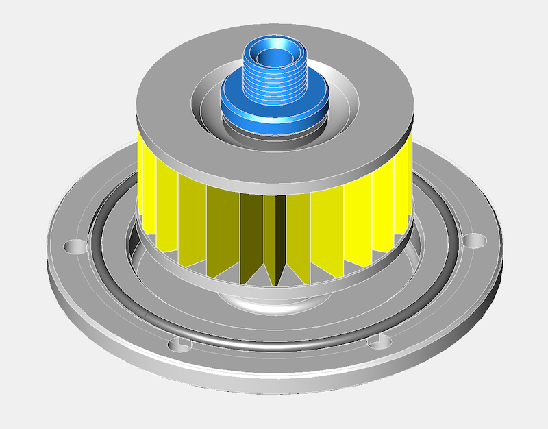
I have updated the CAD drawing to reflect my latest thoughts. I was looking for some oil pump parts and I came across a bag of Viton single lipped seals, which I recognised as some potential front pulley piston ring alternatives I bought five years ago. These seals were bought, as a continuation of the work I did with the rear bearing support seal adaptors, as I always intended to do away with the piston ring seals at either end of the crankshaft. I only made a few of these rear bearing adaptors, and I personally fitted a couple, and then sent some to the Netherlands, as well as a drawing to Germany.
There isn’t a seal that will fit directly into the timing gear cover, as it is a peculiar & unique diameter, so the idea back then was to make a carrier for the seal that would interface into the existing timing gear cover (same idea as the rear system I designed), which had the added bonus of not damaging the OEM timing cover too.This approach does mean a new front pulley assembly will be required, but this is in line with my philosophy of not damaging OEM stock when creating modified components. All the wearing surfaces are also easily replaced in years to come, and readily sourced, plus this system can recover worn timing covers.
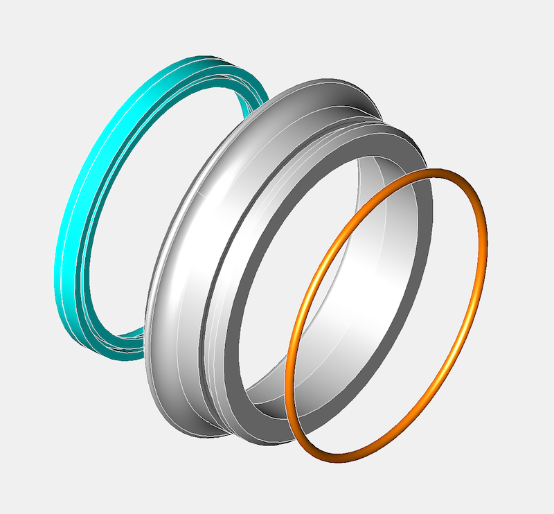
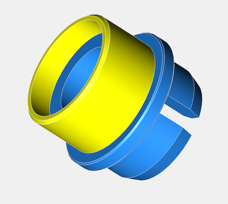
Today, I managed to get the timing gear cover seal diameter surfaces measured on a Elaton Coordinate Measuring Machine, so I now have a very precise idea of what diameter I need to make the new part so that it has a nice interference fit. This is the complete crankshaft conversion kit assembly pictured below.
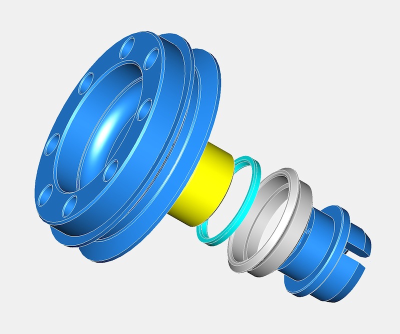
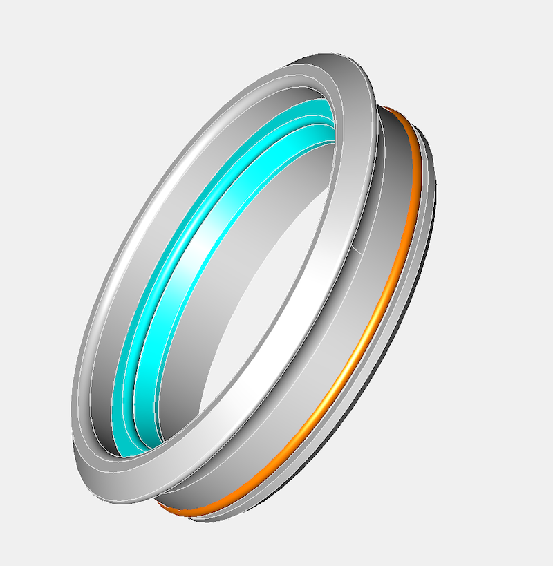
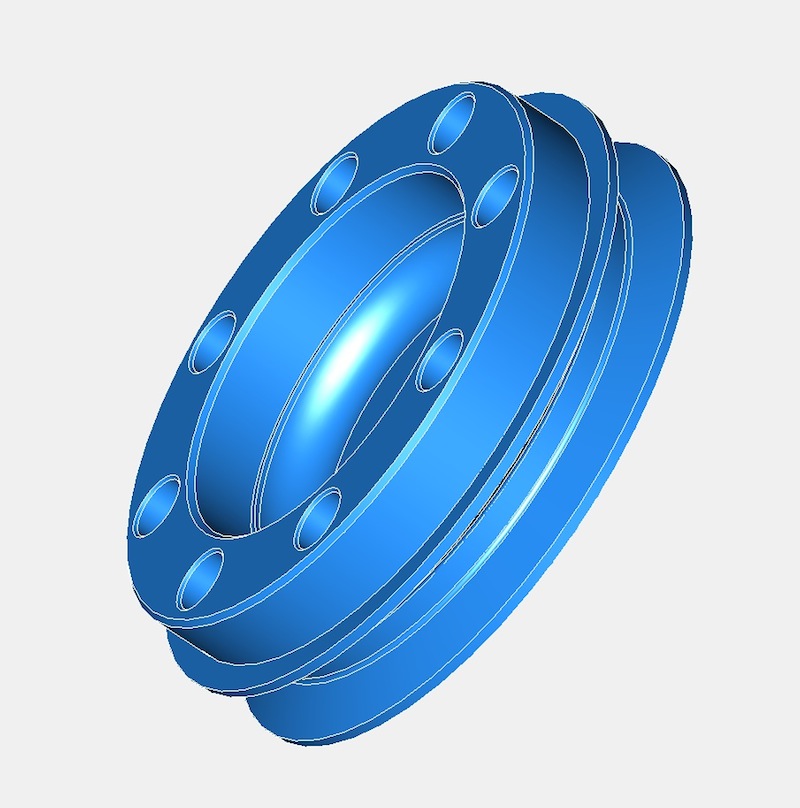
The grey part is the stainless steel seal carrier, and the cyan part the Viton seal. The yellow part is the steel inner ring, which is easily renewed if required, with the blue parts being the aluminium two piece front pulley components. These are located with a small dowel pin, however the parts are held together by the main front pulley crankshaft bolt.
It is necessary to make the parts this way to allow for DIY installations by Panhard owners, and it will be relatively straight forward to fit the conversion kit.
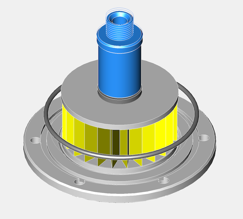
The picture below shows the optional trigger wheel version, which is needed by modern ignition or engine management systems, but fitting these is not for the faint hearted!
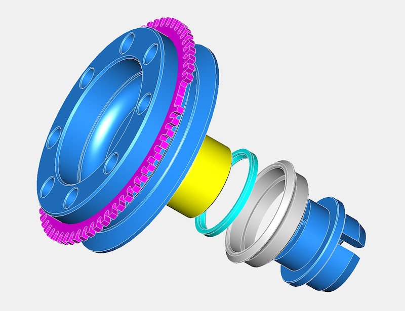
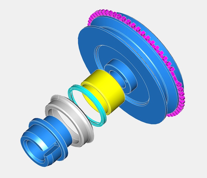
There are different tooth patterns available, but the one in the picture above is a 60-2 trigger wheel, commonly used by Bosch for VAG engines.
There isn’t a seal that will fit directly into the timing gear cover, as it is a peculiar & unique diameter, so the idea back then was to make a carrier for the seal that would interface into the existing timing gear cover (same idea as the rear system I designed), which had the added bonus of not damaging the OEM timing cover too.This approach does mean a new front pulley assembly will be required, but this is in line with my philosophy of not damaging OEM stock when creating modified components. All the wearing surfaces are also easily replaced in years to come, and readily sourced, plus this system can recover worn timing covers.
Today, I managed to get the timing gear cover seal diameter surfaces measured on a Elaton Coordinate Measuring Machine, so I now have a very precise idea of what diameter I need to make the new part so that it has a nice interference fit. This is the complete crankshaft conversion kit assembly pictured below.
The grey part is the stainless steel seal carrier, and the cyan part the Viton seal. The yellow part is the steel inner ring, which is easily renewed if required, with the blue parts being the aluminium two piece front pulley components. These are located with a small dowel pin, however the parts are held together by the main front pulley crankshaft bolt.
It is necessary to make the parts this way to allow for DIY installations by Panhard owners, and it will be relatively straight forward to fit the conversion kit.
The picture below shows the optional trigger wheel version, which is needed by modern ignition or engine management systems, but fitting these is not for the faint hearted!
There are different tooth patterns available, but the one in the picture above is a 60-2 trigger wheel, commonly used by Bosch for VAG engines.
Panhard oil filter variants
Sunday 01 July 2012 Filed in: Panhard Oil
I was updating a few pages and noticed that one of the oil filter prototypes was wrongly labelled. I was doing a retrospective update after finding some photos on another MacBook, when something didn’t add up, and it turned out that I’d been investigating an internal filter variant, as the modified Renault Purflux filters were being discontinued. At this point in time, there were not many alternatives out there, so I was experimenting with internal paper cartridge filters, that I had seen in a local motor factor, and I made a prototype based on my original baseplate.
However with hindsight, it was a red herring, because a few weeks later I found a Mann Hummel external filter, that was better than the Purflux derived Renault unit, but the internal solution still has merit, especially in a double sump increased oil capacity format, which is a necessity to reduce the engine oil temperatures and increase the oil quality.
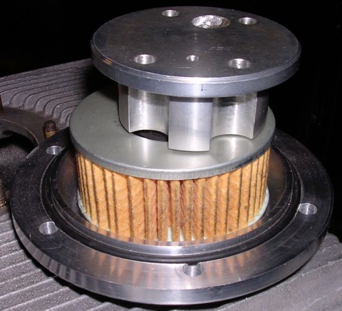
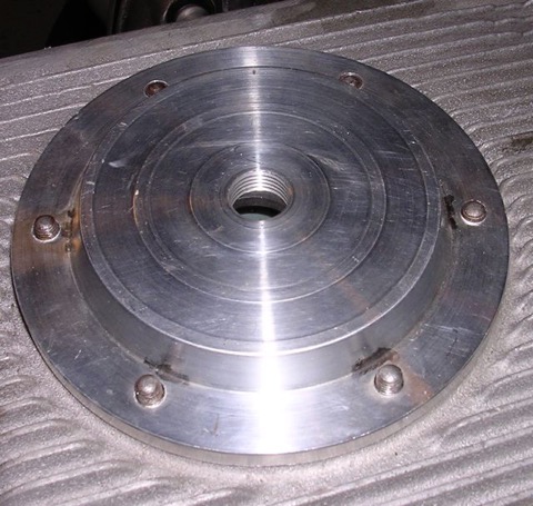
After looking at this some more, I have decided to remanufacture this variant, as it offers a different solution for the factory Panhard car, and can be used with double sump versions too. It does not hang down as far as the cartridge, which is important because the ground clearance under the engine is reduced by 50mm after fitting the factory double sump. The actual ground clearance doesn’t change however, but fitting a sump or a cartridge filter appears to lower it in some peoples’ eyes.
Further plus points are, a magnetic sump plug can also be incorporated into the sump plate if required, the filter is freely available from motor factors in Europe, and the oil filter cartridge doesn’t need to be modified, which simplifies things further for the less dextrous. Technically it’s also easier for people to understand, as the paper filter is a straight swap for the original mesh filter, although the low flow rate & low pressure drop through a paper element principle still applies.
Latest CAD shown below, but it’s work in progress.
As I have been looking at the double sump variant for Brian Osbourne’s latest engine, it’s logical to try and use some of this for the next generation solution. I don’t have a double pump available at the moment, otherwise I would check whether I could use this new sump plate for the internal filter version with the double pump double sump application. I do know somebody with one, so I am going to take an internal filter and sump plate to their engine and see what is required, but it will have to wait until after the International Citröen Car Club 2012 Rally at Harrogate.
Latest thoughts in CAD for the double sump version, but only using the original oil pump, which is more than adequate assuming the crankcase oil circuits are modified. This version has a different pick up pipe and a flat not dished sump plate, so it will need two new parts.
However with hindsight, it was a red herring, because a few weeks later I found a Mann Hummel external filter, that was better than the Purflux derived Renault unit, but the internal solution still has merit, especially in a double sump increased oil capacity format, which is a necessity to reduce the engine oil temperatures and increase the oil quality.
After looking at this some more, I have decided to remanufacture this variant, as it offers a different solution for the factory Panhard car, and can be used with double sump versions too. It does not hang down as far as the cartridge, which is important because the ground clearance under the engine is reduced by 50mm after fitting the factory double sump. The actual ground clearance doesn’t change however, but fitting a sump or a cartridge filter appears to lower it in some peoples’ eyes.
Further plus points are, a magnetic sump plug can also be incorporated into the sump plate if required, the filter is freely available from motor factors in Europe, and the oil filter cartridge doesn’t need to be modified, which simplifies things further for the less dextrous. Technically it’s also easier for people to understand, as the paper filter is a straight swap for the original mesh filter, although the low flow rate & low pressure drop through a paper element principle still applies.
Latest CAD shown below, but it’s work in progress.
As I have been looking at the double sump variant for Brian Osbourne’s latest engine, it’s logical to try and use some of this for the next generation solution. I don’t have a double pump available at the moment, otherwise I would check whether I could use this new sump plate for the internal filter version with the double pump double sump application. I do know somebody with one, so I am going to take an internal filter and sump plate to their engine and see what is required, but it will have to wait until after the International Citröen Car Club 2012 Rally at Harrogate.
Latest thoughts in CAD for the double sump version, but only using the original oil pump, which is more than adequate assuming the crankcase oil circuits are modified. This version has a different pick up pipe and a flat not dished sump plate, so it will need two new parts.
Panhard piston update
Monday 11 June 2012 Filed in: Panhard Piston
Just had an update from the piston company, and they have sent me a grainy picture of the piston part finished.
The underside still needs machining, and the barrelling etc is still to do, but it’ll give an idea of how much shorter & lighter the piston will be.
The underside still needs machining, and the barrelling etc is still to do, but it’ll give an idea of how much shorter & lighter the piston will be.
Panhard musings
Monday 07 May 2012 Filed in: Blog Comments
I collected another Panhard crankshaft the other day to true up and lock in place, as it’s definitely not running concentric. It looks like the crank has turned ever so slightly on the crank pins and has a rather eccentric wobble.
As I am doing another crankshaft repair for Brian, I thought I’d compare the two, and at least this new crank confirms the other is too long between the bearings. In the discussions I had with the owner, I was bemused that somebody can spend a lot of money on bodywork and then baulk at the price of an engine.
Any engine that is going to get reconditioned will cost far more than swapping out for another. Its inevitable that the economics of doing so are questionable, but when you are faced with an older engine that is flawed, you’d think that would push the argument towards reconditioning, instead of just making do with any lump to hand.
In the case of the Panhard flat twin, unless you mod the lubrication circuits and increase the oil capacity you will be forever into a rebuild cycle, as these engines have some basic design faults. Panhard never had the money to eradicate these deficiencies, and whereas the engine initially was well designed, its’ subsequent development (to combat service faults) by different Panhard employees was not up to scratch as they missed the basics.
Unfortunately, very few people can see this point of view, and they seem to think you have to look to Panhards’ homeland for the best solutions, but there are no boundaries to good engineering or design. The UK has been a hub of motorsport development ever since Panhard started on their slippery slope to closure, and during this period British companies have seen dominance in World Rally cars and Formula 1. All this activity spins down to the lowest forms of motorsport, such as karting and clubman racing, and is also reflected in specialist educational courses available at the universities.
Nobody is suggesting that Panhards need F1 technology, but the companies that make parts for this industry have a huge expertise in material technology and manufacturing that can be applied to our engines, but only if you are open minded.
I hope over the next few months to surprise at least one person with the things I am working on, drop me a line if you are interested too.