Panhard Ignition
Panhard ignition - Imfsoft Master Mini 3TCI
Saturday 20 September 2014
After getting back from Belgium, I started to revisit the Master Mini 3TCI that was working on the test rig before I left.
Unfortunately, I had a firmware glitch that was stopping it writing to the ROM chip, aka the “FLASH” in Czech speak, but of course I didn’t know this. I had uploaded the latest version previously, but as I was getting frustrated, I resurrected a Windows 7 laptop and installed the Imfsoft software direct from the website, and the pages that referred to the Master Mini 3TCI. Upon opening it, the MASTER software looked different, so I reset the wheel parameters, and wrote to the RAM & ROM, disconnected the power, and read the ROM. It stayed the same, whereas the MacBook running XP SP3 in Parallels 9 was corrupting the unit. I was getting loads of “-128” values in boxes, when previously they were blank.
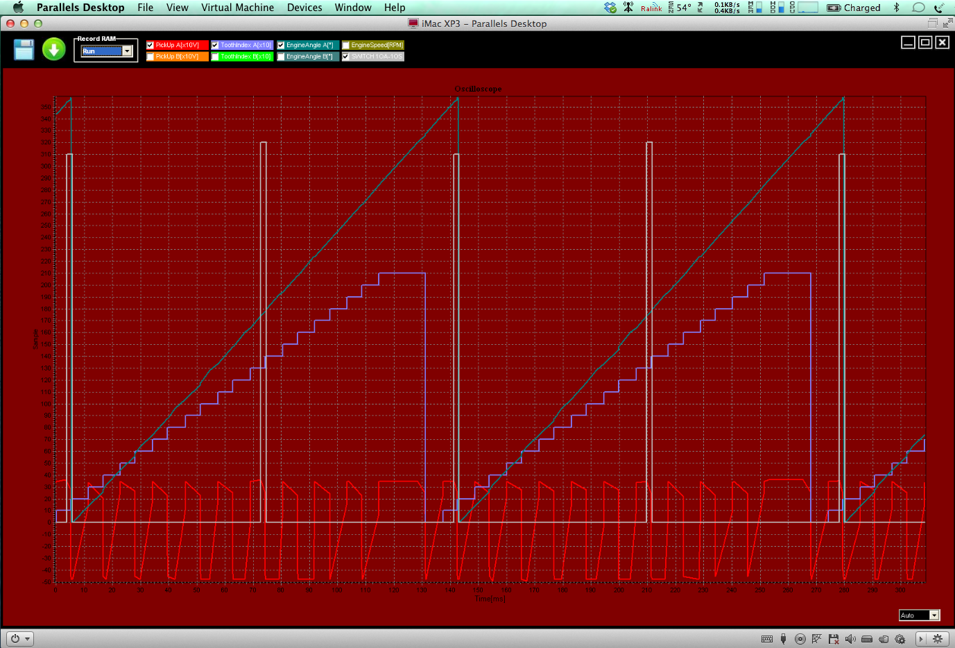
After doing a few oscilloscope traces of the trigger wheel in action at various speeds, and having no problems, I rebooted the MacBook with the same firmware and wrote it to the MASTER Mini...voilà c’est parfait.
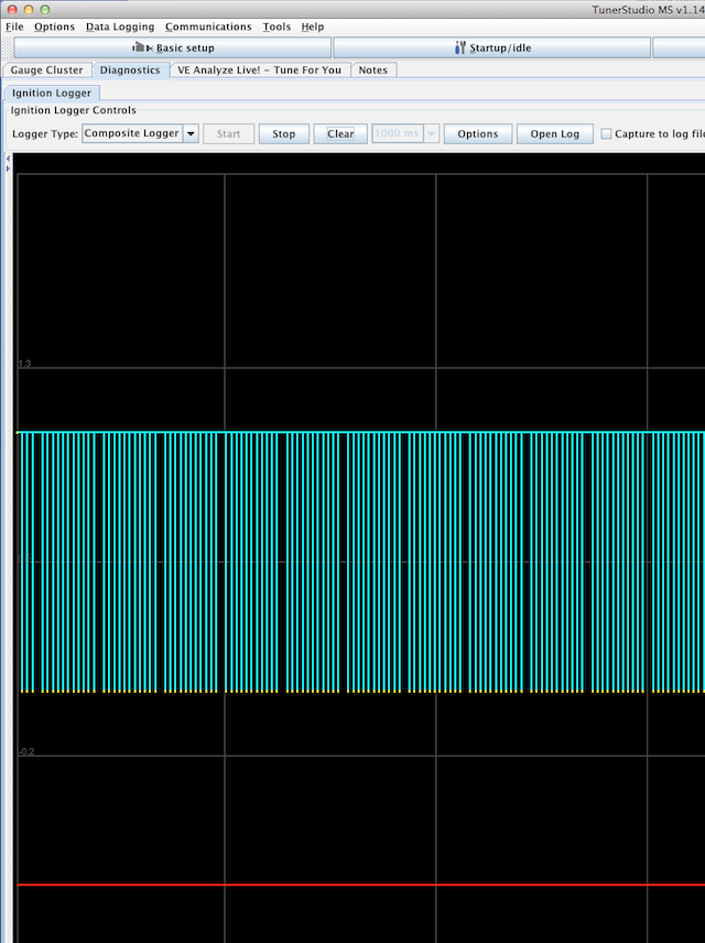
Here’s a few screenshots from the MacBook, at different speeds. the lowest recorded cranking speed was 40 rpm!
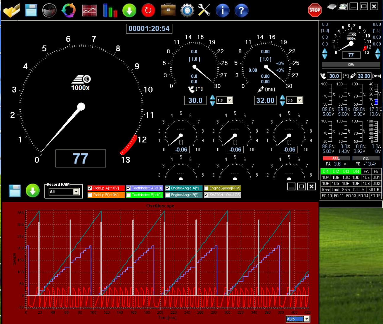
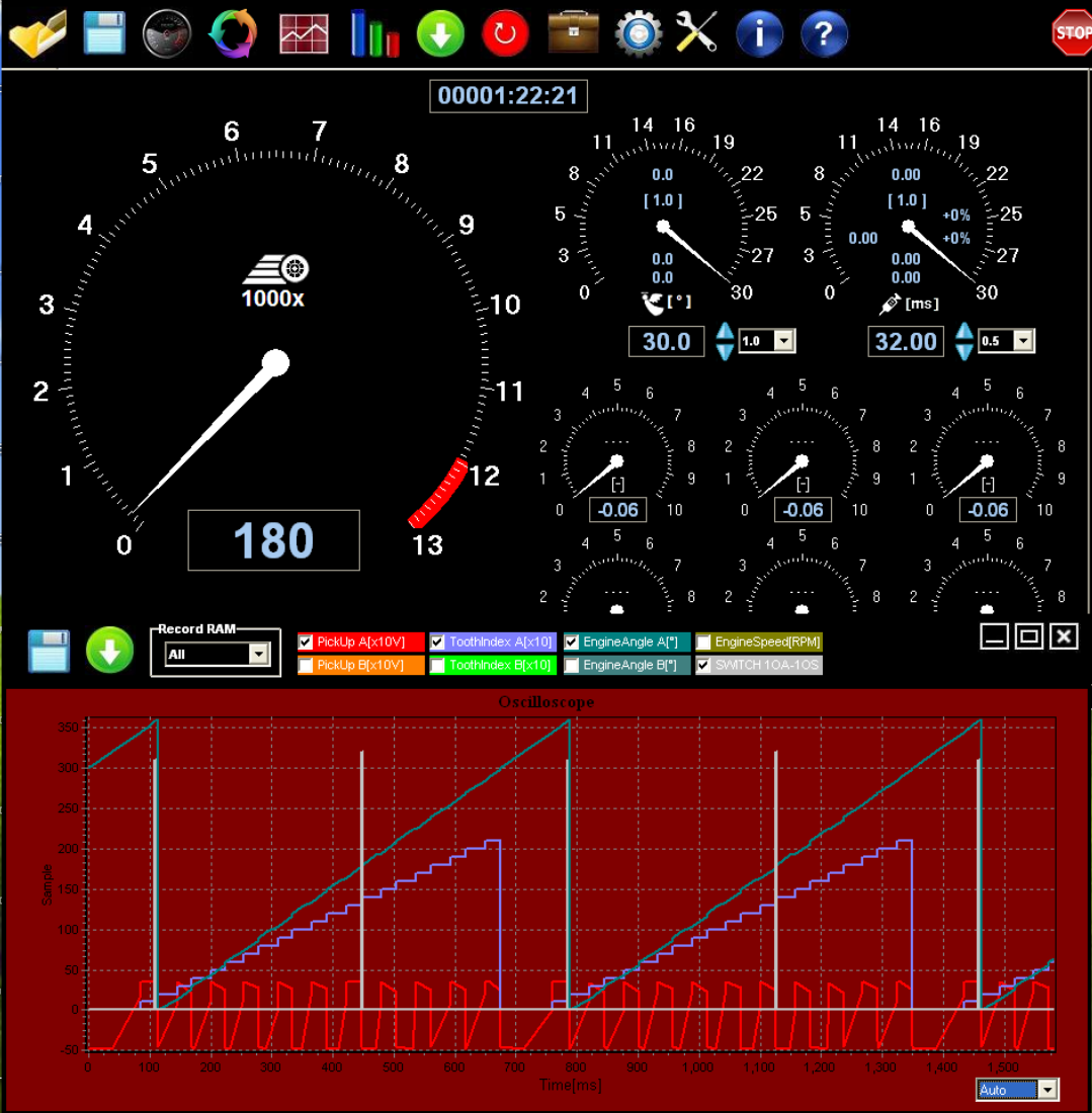
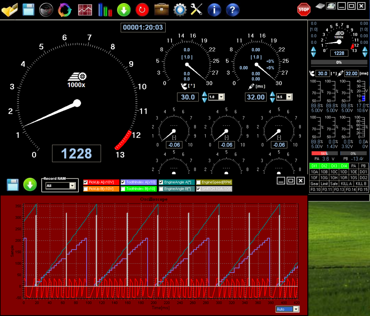
The red trace at the bottom is the trigger wheel going past the sensor, the white columns are the ignition events for the coil switching, so you can see two per revolution. So it’s all looking good again. Next test is check at what range of air gap I can tolerate, and not lose reliable triggering, but that’ll be another day.
Unfortunately, I had a firmware glitch that was stopping it writing to the ROM chip, aka the “FLASH” in Czech speak, but of course I didn’t know this. I had uploaded the latest version previously, but as I was getting frustrated, I resurrected a Windows 7 laptop and installed the Imfsoft software direct from the website, and the pages that referred to the Master Mini 3TCI. Upon opening it, the MASTER software looked different, so I reset the wheel parameters, and wrote to the RAM & ROM, disconnected the power, and read the ROM. It stayed the same, whereas the MacBook running XP SP3 in Parallels 9 was corrupting the unit. I was getting loads of “-128” values in boxes, when previously they were blank.
After doing a few oscilloscope traces of the trigger wheel in action at various speeds, and having no problems, I rebooted the MacBook with the same firmware and wrote it to the MASTER Mini...voilà c’est parfait.
Here’s a few screenshots from the MacBook, at different speeds. the lowest recorded cranking speed was 40 rpm!
The red trace at the bottom is the trigger wheel going past the sensor, the white columns are the ignition events for the coil switching, so you can see two per revolution. So it’s all looking good again. Next test is check at what range of air gap I can tolerate, and not lose reliable triggering, but that’ll be another day.
Comments
Panhard ignition update
Wednesday 17 September 2014
The ignition version of the timing cover has to be reworked, as Imfsoft do not make the Direct Ignition TCI model anymore, but a new unit called the Master Mini 3TCI. To adapt my existing two sensor covers I have made a blanking plug, and the thoughts at the moment are, that only one or no hole version of the cover will be produced, with a distinct possibility that the plain cover will be the ignition variant with a blanking plug fitted.
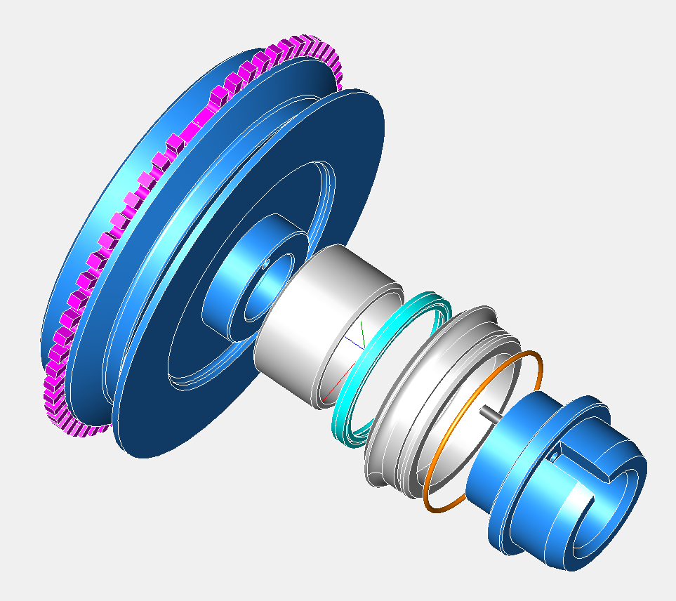
Here’s how it looks at the moment...the V pulley is an optional part, for those that cannot modify the front pulley themselves.
The timing cover is primarily a front seal upgrade option, so the ignition aspect is a secondary upgrade.
The Imfsoft Master Mini 3TCI has been bench tested and produces very good results, as can be seen here. The red waveform at the bottom is the teeth from the trigger wheel, the light blue “stairs” that step upwards are the incrementing trigger events, and these need to be regular steps. The diagonal greenish line is the processor interpreting the wheel, and the software is checking that these are the correct spacings. The white columns are twice per camshaft revolution and are the ignition events that trigger the coils.
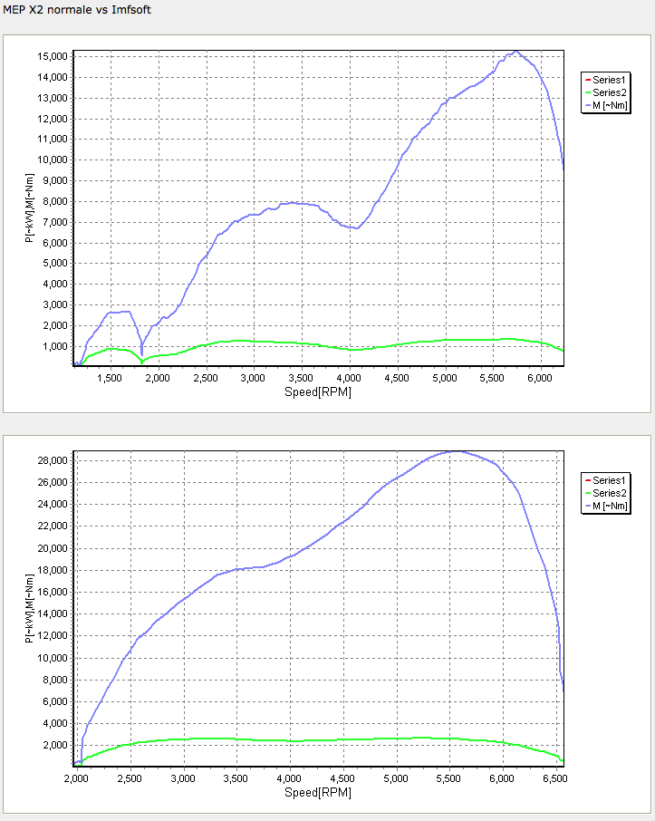
At the moment, I don’t have a working engine, so I have fitted the Imfsoft to an MEP X2 recently. This used the earlier Imfsoft unit, but it has a very useful “dyno” function. The units are meaningless on the right hand side representing “Power”, but the shaping of the curve is representational. The first one is a standard Panhard M8S engine fitted with the original vacuum & centrifugal advance system, and the next curve is the first Imfsoft run where a modified advance curve affected the power output of the engine.
Early days yet, but interesting to say the least, and it backs up my earlier research with Ron Tyrrell’s PL17 where I modified the distributor. I could get a change in part throttle performance at the expense of full throttle or cruising. The mechanical system isn’t able to cope with the demands of the engine, whereas a correctly set up programmable system is.
Watch this space...
Panhard Ignition Improvements
Tuesday 04 June 2013
I have discussed the oil modifications in some detail over the years, but the next big area of improvement is the ignition.
The Panhard ignition was a distributor based system, that used a rotor arm to give a cylinder 1, cylinder 2 sequential output. There were two types of distributor fitted, vacuum only, and centrifugal & vacuum, but whatever type it is nowadays, the distributor will almost certainly be worn. I first noticed this in Ron Tyrrell’s car when I reversed the vacuum canister on his distributor to improve the running. Later I made a 123 ignition prototype distributor, but a board failure stopped the project.
It is quite common for this to be replaced with a Citroen 2CV coil, triggered by the points to create a wasted spark system, where cylinder 1 & 2 “fire” together, but the strongest spark is biased towards the cylinder with the most compression, which is full of the fuel air mix.
Other systems have been devised over the years of production, Hampe fitted twin contact breakers for twin plugging (although this was a wasted system for reliability), and some DB racers had a cam based triggering system from a special front cover. I found this out at Almen from Joel Brunel.
Whilst I was in Belgium, I got first hand knowledge of the distributor wear problem, when I was watching Stefaan timing up a MEP racer. This is basically a Tigre Panhard engine with a slightly different carburettor and manifold, but the distributor was a Ducellier vacuum & centrifugal type. He was running up the engine, setting the static advance based on the flywheel position, and getting a sluggish engine. In the end after disconnecting the vacuum, and measuring the centrifugal advance it was close on 28º and sticking, the vacuum was 23º, and static was an additional 21-31º. All these values are added together, so you could get close to 75º advance if you followed the manual.
Maximum advance for a Panhard engined racing sidecar running twin Amal carburettors was close on 32º, using high octane fuel, but burning modern pump fuel, the cars need a lot less than OEM. In fact, driving Sonia’s car & Brian’s whilst it was running, my static was around 10º to give nice off the throttle response, but at higher rpms, it could do with even less. Ron Tyrrell’s car has a manual advance and retard cable, a bit like a choke cable, which allows for variations to be made when running, and you do have to use it to make the engine more responsive under load. All of this tells you that the original Panhard ignition advance curve is not matched to present day fuels.
How would you go about to change this?
The obvious approach is modify the distributor, and Peter Breed does this, with a very nice 123 derived system. I actually did this years earlier, but the circuit board was too big, and so I had to make a new distributor casing. A distributor based system is still a good solution for some people, but it lacks accuracy, so modern cars use a more direct approach, mainly because of emissions, and the need to control things better.
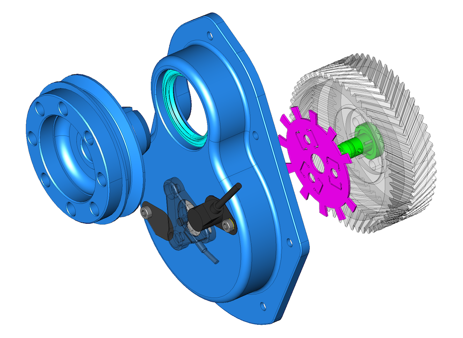
Some earlier cars used a crankshaft sensor, using either the flywheel, a front pulley or a crankshaft web, and wasted spark coils. I did look at flywheel sensing for the Panhard engine, and it was the need to develop an easy to fit kit that negated this, so this is why I went down the modified pulley route, as shown below.
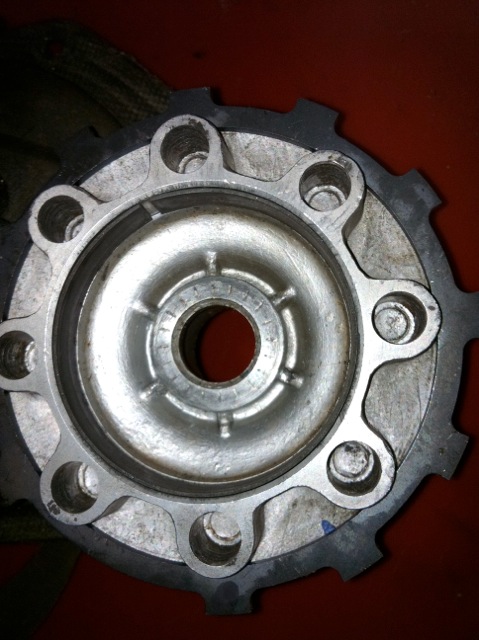
If you look at the components required to make an easy to fit kit, the cost is starting to go far too high, so I had to come up with a better idea. The biggest single flaw, was the lack of camshaft position sensing, which meant another set up to do this. On modern cars with overhead camshafts, it’s relatively easy to sense the cam lobe via a hole in the camshaft cover or a trigger wheel on the camshaft belt drive pulley, but on a Panhard pushrod engine, things are at first a little more complicated, as there doesn’t seem to be a suitable position to place one on the cylinder. It was only after I exhausted the camshaft sensor location possibilities, that I decided a trigger off the camshaft timing gear would be best and least expensive way to modify the ignition on these cars, because it would need only one part to be modified.
Camshaft triggering is often combined with crankshaft or flywheel triggering to make a higher level of precision on multi cylinder cars or motorcycles, and often this is used to create sequential information, so now the engine management knows what stroke the cylinder is on, which just replicates what the distributor cap and contact breaker system did originally. However, when you look at the spark events, you can use a simpler camshaft trigger will suffice, as the Panhard engine is unlikely to exceed 6500 rpm, and it only has two cylinder to ignite. It could even be modified further to provide more accurate rotational information, by fitting a toothed wheel, so it became a “no brainer” to not take this further.
However, I needed to identify the easiest area to locate a sensor and trigger, and it soon became apparent, that although I could modify the existing pressed metal timing gear cover, it would be a struggle for most people. After a large amount of CAD work, and experimenting with different sensor types, a new timing cover was developed, and this also includes a new front seal detail, but only after an easy mod to the front pulley. This new part creates an accurate highly reliable triggering system, but it does require the fitting of the aluminium camshaft gear aka “alu pignon”, as well as fitting a steel inner ring to the front pulley. It is a big step forward in modernising the engines, without detracting from their originality, and allows them to run better with modern fuels.
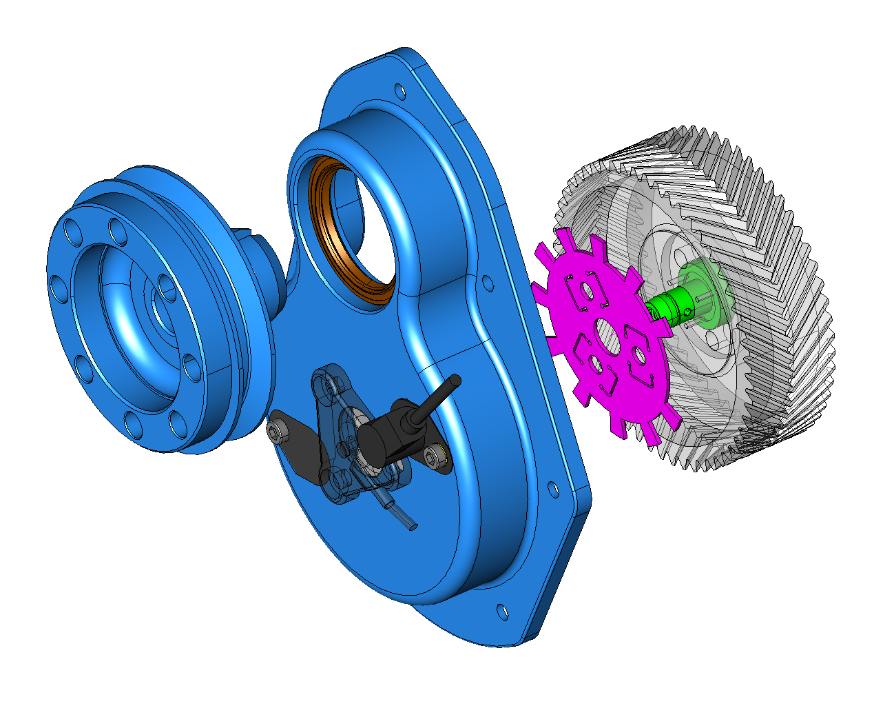
The latest version is here…this is designed for a MicroSquirt or Imfsoft Master Mini 3TCI
The part uses liquid gasket to seal the timing cover to the crankcase, and the original oil slinger parts, that diverted the oil from the piston ring oil seal are not required, a small laser cut spacer is used instead. The front crankshaft oil seal has an outer diameter of 65mm, which allows for a large variance in inner ring sizes to be used on the front pulley, as some Panhardistes have made modifications to this area already.
I recommend a 50 x 65 x 8 Viton oil seal, and a IR 45 x 50 x 15 inner ring.
The Panhard ignition was a distributor based system, that used a rotor arm to give a cylinder 1, cylinder 2 sequential output. There were two types of distributor fitted, vacuum only, and centrifugal & vacuum, but whatever type it is nowadays, the distributor will almost certainly be worn. I first noticed this in Ron Tyrrell’s car when I reversed the vacuum canister on his distributor to improve the running. Later I made a 123 ignition prototype distributor, but a board failure stopped the project.
It is quite common for this to be replaced with a Citroen 2CV coil, triggered by the points to create a wasted spark system, where cylinder 1 & 2 “fire” together, but the strongest spark is biased towards the cylinder with the most compression, which is full of the fuel air mix.
Other systems have been devised over the years of production, Hampe fitted twin contact breakers for twin plugging (although this was a wasted system for reliability), and some DB racers had a cam based triggering system from a special front cover. I found this out at Almen from Joel Brunel.
Whilst I was in Belgium, I got first hand knowledge of the distributor wear problem, when I was watching Stefaan timing up a MEP racer. This is basically a Tigre Panhard engine with a slightly different carburettor and manifold, but the distributor was a Ducellier vacuum & centrifugal type. He was running up the engine, setting the static advance based on the flywheel position, and getting a sluggish engine. In the end after disconnecting the vacuum, and measuring the centrifugal advance it was close on 28º and sticking, the vacuum was 23º, and static was an additional 21-31º. All these values are added together, so you could get close to 75º advance if you followed the manual.
Maximum advance for a Panhard engined racing sidecar running twin Amal carburettors was close on 32º, using high octane fuel, but burning modern pump fuel, the cars need a lot less than OEM. In fact, driving Sonia’s car & Brian’s whilst it was running, my static was around 10º to give nice off the throttle response, but at higher rpms, it could do with even less. Ron Tyrrell’s car has a manual advance and retard cable, a bit like a choke cable, which allows for variations to be made when running, and you do have to use it to make the engine more responsive under load. All of this tells you that the original Panhard ignition advance curve is not matched to present day fuels.
How would you go about to change this?
The obvious approach is modify the distributor, and Peter Breed does this, with a very nice 123 derived system. I actually did this years earlier, but the circuit board was too big, and so I had to make a new distributor casing. A distributor based system is still a good solution for some people, but it lacks accuracy, so modern cars use a more direct approach, mainly because of emissions, and the need to control things better.
Some earlier cars used a crankshaft sensor, using either the flywheel, a front pulley or a crankshaft web, and wasted spark coils. I did look at flywheel sensing for the Panhard engine, and it was the need to develop an easy to fit kit that negated this, so this is why I went down the modified pulley route, as shown below.
If you look at the components required to make an easy to fit kit, the cost is starting to go far too high, so I had to come up with a better idea. The biggest single flaw, was the lack of camshaft position sensing, which meant another set up to do this. On modern cars with overhead camshafts, it’s relatively easy to sense the cam lobe via a hole in the camshaft cover or a trigger wheel on the camshaft belt drive pulley, but on a Panhard pushrod engine, things are at first a little more complicated, as there doesn’t seem to be a suitable position to place one on the cylinder. It was only after I exhausted the camshaft sensor location possibilities, that I decided a trigger off the camshaft timing gear would be best and least expensive way to modify the ignition on these cars, because it would need only one part to be modified.
Camshaft triggering is often combined with crankshaft or flywheel triggering to make a higher level of precision on multi cylinder cars or motorcycles, and often this is used to create sequential information, so now the engine management knows what stroke the cylinder is on, which just replicates what the distributor cap and contact breaker system did originally. However, when you look at the spark events, you can use a simpler camshaft trigger will suffice, as the Panhard engine is unlikely to exceed 6500 rpm, and it only has two cylinder to ignite. It could even be modified further to provide more accurate rotational information, by fitting a toothed wheel, so it became a “no brainer” to not take this further.
However, I needed to identify the easiest area to locate a sensor and trigger, and it soon became apparent, that although I could modify the existing pressed metal timing gear cover, it would be a struggle for most people. After a large amount of CAD work, and experimenting with different sensor types, a new timing cover was developed, and this also includes a new front seal detail, but only after an easy mod to the front pulley. This new part creates an accurate highly reliable triggering system, but it does require the fitting of the aluminium camshaft gear aka “alu pignon”, as well as fitting a steel inner ring to the front pulley. It is a big step forward in modernising the engines, without detracting from their originality, and allows them to run better with modern fuels.
The latest version is here…this is designed for a MicroSquirt or Imfsoft Master Mini 3TCI
The part uses liquid gasket to seal the timing cover to the crankcase, and the original oil slinger parts, that diverted the oil from the piston ring oil seal are not required, a small laser cut spacer is used instead. The front crankshaft oil seal has an outer diameter of 65mm, which allows for a large variance in inner ring sizes to be used on the front pulley, as some Panhardistes have made modifications to this area already.
I recommend a 50 x 65 x 8 Viton oil seal, and a IR 45 x 50 x 15 inner ring.
Panhard Ignition Prototypes
Sunday 08 April 2012
I have had a nice update from Peter Breed, who says his ignition prototype is looking good. This will be a switchable two curve fully electronic set up that will be contained within the OEM distributor.
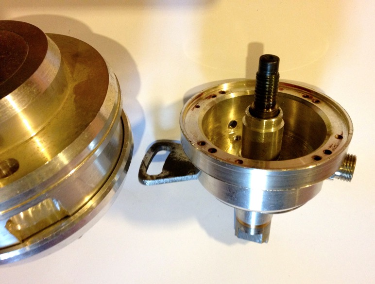
Like I said previously, I made several prototype ignitions in 2002, but the existing distributor couldn’t be used as it was too small a diameter to fit the circular board. My ignition prototypes were based on a 123ignition unit, sold as a Citröen 2CV Formula Bleu kit, pictured below, which incidentally was supplied by Ron Tyrrell.
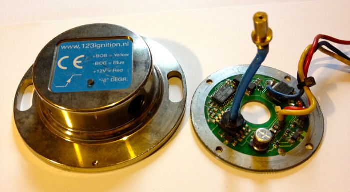
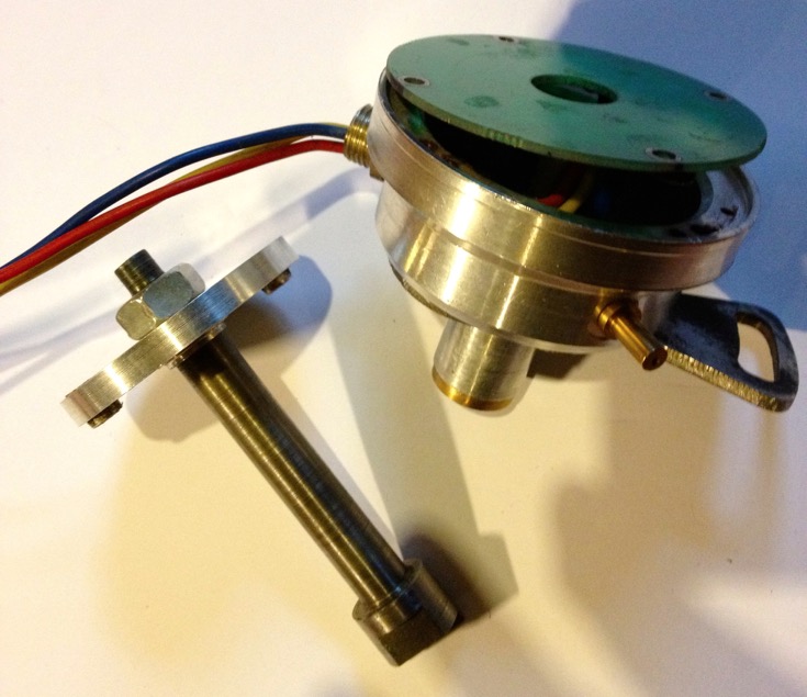
I soon made an adaptor to take the standard 2CV unit, as well as a new driveshaft complete with magnets, body shown below.
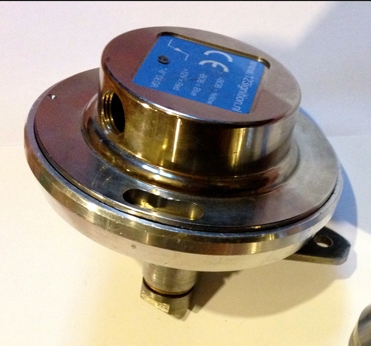
There is a big problem with this set up, as the circuits design rotation is the wrong way for the engine, which incidentally was a stumbling block for 123 designers at the time too. Fortunately I realised if I flipped the board the magnetic field would pass through the circuit board and the rotation would be effectively reversed, so I made a new model to test the idea, which was just a spacer sandwiched between the two previous halves, and a new spindle to take the magnets.
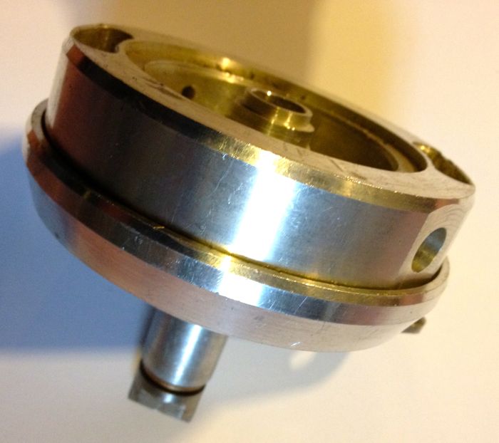
Now the board and magnets were in the base not the lid like with the 2CV set up, and also the 123 lid wasn’t needed. I had to put a bearing in the top, to stop the wobble about the spindle, so I ended up with a rather large lump initially.
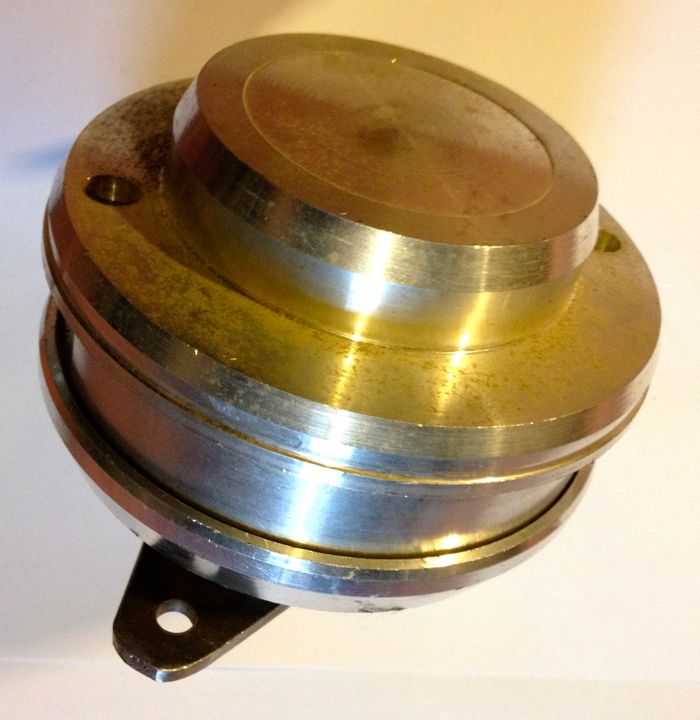
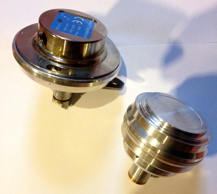
It wasn’t really surprising it ended up so large, but whereas I was making a conversion unit for the 123ignition kit before, I now had an opportunity to explore other options, and just use the basic component board.
So having tested the set up made a spark, using my motorised ignition rig, I made a new prototype, that ended being another version a couple of days later, but at least it was getting smaller. I incorporated the original 123 vacuum advance pick up into this version too, but the biggest drawback was I would have to up the ante again to fit the rev counter drive.
I wasn’t able to cut a gear drive for the tachometer drive like the SEV distributor needed and the economics were such that it wash’t viable to continue as it couldn’t meet the affordable target price.
Still it was starting to look a lot more designed, and this is were I left off about 9 years ago.
After the unit developed an electrical glitch, it was placed in a bag and left to gather dust, but by then the ignitions had taken a different turn with my MicroSquirt DIY EFI developments for the GTS1000. I would probably still retain the distributor for the tachometer drive, but use crankshaft based triggering off the front pulley, as it’s more precise and removes all the backlash and slop in the existing set up, which uses two sets of gears and two dog drives just to get to the contact breaker cam.
Interestingly, it has taken this long for 123ignitions to develop a smaller circuit board, but in the meantime they have developed a huge host of distributor based products for the more popular models out there, and these are quality products. I notice they have started to develop a DIY programmable interface for some of their products, but I don’t see any mention of the multispark set up one of the guys at 123 was working on at the time of my involvement.
Like I said previously, I made several prototype ignitions in 2002, but the existing distributor couldn’t be used as it was too small a diameter to fit the circular board. My ignition prototypes were based on a 123ignition unit, sold as a Citröen 2CV Formula Bleu kit, pictured below, which incidentally was supplied by Ron Tyrrell.
I soon made an adaptor to take the standard 2CV unit, as well as a new driveshaft complete with magnets, body shown below.
There is a big problem with this set up, as the circuits design rotation is the wrong way for the engine, which incidentally was a stumbling block for 123 designers at the time too. Fortunately I realised if I flipped the board the magnetic field would pass through the circuit board and the rotation would be effectively reversed, so I made a new model to test the idea, which was just a spacer sandwiched between the two previous halves, and a new spindle to take the magnets.
Now the board and magnets were in the base not the lid like with the 2CV set up, and also the 123 lid wasn’t needed. I had to put a bearing in the top, to stop the wobble about the spindle, so I ended up with a rather large lump initially.
It wasn’t really surprising it ended up so large, but whereas I was making a conversion unit for the 123ignition kit before, I now had an opportunity to explore other options, and just use the basic component board.
So having tested the set up made a spark, using my motorised ignition rig, I made a new prototype, that ended being another version a couple of days later, but at least it was getting smaller. I incorporated the original 123 vacuum advance pick up into this version too, but the biggest drawback was I would have to up the ante again to fit the rev counter drive.
I wasn’t able to cut a gear drive for the tachometer drive like the SEV distributor needed and the economics were such that it wash’t viable to continue as it couldn’t meet the affordable target price.
Still it was starting to look a lot more designed, and this is were I left off about 9 years ago.
After the unit developed an electrical glitch, it was placed in a bag and left to gather dust, but by then the ignitions had taken a different turn with my MicroSquirt DIY EFI developments for the GTS1000. I would probably still retain the distributor for the tachometer drive, but use crankshaft based triggering off the front pulley, as it’s more precise and removes all the backlash and slop in the existing set up, which uses two sets of gears and two dog drives just to get to the contact breaker cam.
Interestingly, it has taken this long for 123ignitions to develop a smaller circuit board, but in the meantime they have developed a huge host of distributor based products for the more popular models out there, and these are quality products. I notice they have started to develop a DIY programmable interface for some of their products, but I don’t see any mention of the multispark set up one of the guys at 123 was working on at the time of my involvement.
Panhard trigger wheel testing
Sunday 02 October 2011
Another few hours spent on this, testing various iterations of the firmwares with my cased MicroSquirts, and revisiting yesterdays efforts, as I made a number of teeth input error part way through my previous attempts. This only affects the early B&G firmware and MSExtra as they need the correct value inputting, whereas the later B&G 3.760 has an auto detect function called Auto Trigger.
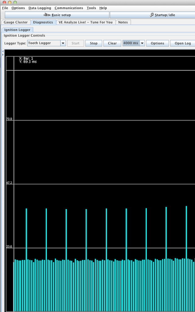
A quick screenshot of TunerStudio doing its stuff using the logging tools. The cyan columns are the 11 teeth, the gap the 12th missing tooth, and the red line on the bottom is the Sync errors, and because this line is straight there are none. Using MSExtra 3.1.0, I can get reliable sync from 45 rpm up to 11800 rpm using the Renault sensor and a 2mm air gap. I think if the trigger wheel is made thicker, it will allow me to increase the air gap to nearer 3mm, and I might make the teeth slightly less wide too.
The screenshot below shows the tooth pattern, the 11vertical lines roughly the same size are the physical bumps or teeth, and the tallest column is the missing tooth area. This is what the ECU is seeing, but as this is using the motorised engine rig, so the variances between the 11 teeth are not very pronounced. However when this is used on a real engine the compression effects and the resulting slowing down of the trigger wheel attached to the crankshaft, shows itself in bigger variances in height.
Panhard crankshaft pulley on EFI rig
Saturday 01 October 2011
I managed to get a few timing wheels laser cut the other day, and the idea was to combine these with a Renault crankshaft sensor, so that I can create a timing trigger for the electronic ignition. I had done this with an earlier project, but now wanted to refine the set up further to allow for the fuel injection mods that will follow from this.
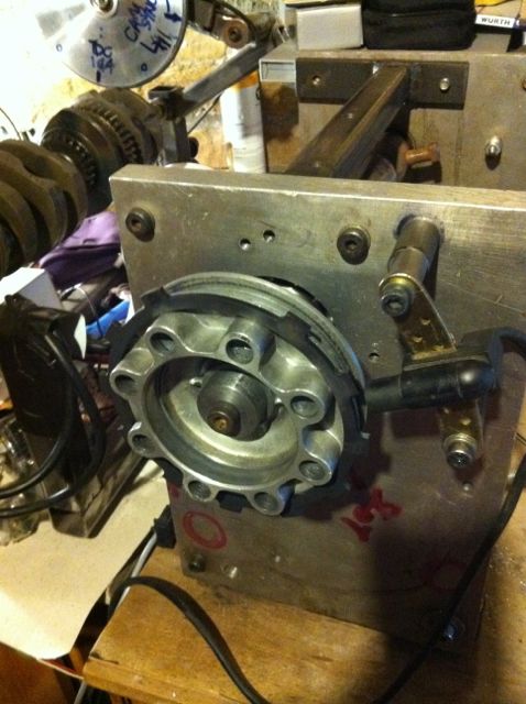
Here’s a pic of the first design effort, and there’s me thinking that a 3mm thick wheel would be sufficient for a 2mm sensor tip. At first it didn’t seem like it would be, and the disturbing thing is there is a slight eccentricity with these OEM pulleys, so a wider wheel might be useful to combat this. The reason why it wasn’t working as well as it should have done, was because I was putting the wrong values into the Number of Teeth box. I was inputting 8-1, when it was plainly a 12-1 wheel!

I was also swapping various v2 MicroSquirts & a v3 beta running different EFI firmwares including MSExtra 3.1 and, B&G 2.890, 3.430 & 3.760.
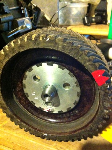
This 12-1 wheel design worked OK up to 3000 rpm, but then dropped out of sync, whereas the 6mm thick 36-1 wheel using the same sensor worked faultlessly from 50-11780 rpm, so despite the initial input error, the trigger wheel is too thin.
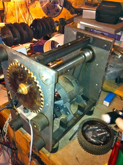
This is the old washing machine motor from a 1986 Hotpoint ℅ Siemens Gmbh dropped into my DIY engine rig. I have had to fit a poly-vee belt reduction gear, as this thing will rev to 22,000 RPM in 1:1 mode!
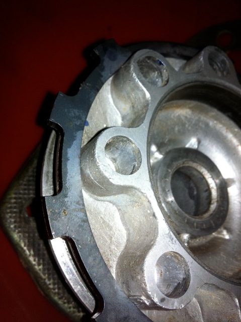
Note. Bottom right, inside the chevron cut fibre camshaft timing gear are the revised oil light pistons I made in the 1990’s to combat the lubrication faults with the Panhard engine. The picture below shows an incomplete one, with the revised lubrication to the timing gear (there is a relief valve, ball, spring with a set screw yet to be inserted in the middle).
Also can you spot the crankshaft & cam rig in the background, above this picture, which is still being used to develop the MicroSquirt based EFI systems for the GTS1000 & Thunderace motorcycle engines
Here’s a pic of the first design effort, and there’s me thinking that a 3mm thick wheel would be sufficient for a 2mm sensor tip. At first it didn’t seem like it would be, and the disturbing thing is there is a slight eccentricity with these OEM pulleys, so a wider wheel might be useful to combat this. The reason why it wasn’t working as well as it should have done, was because I was putting the wrong values into the Number of Teeth box. I was inputting 8-1, when it was plainly a 12-1 wheel!
I was also swapping various v2 MicroSquirts & a v3 beta running different EFI firmwares including MSExtra 3.1 and, B&G 2.890, 3.430 & 3.760.
This 12-1 wheel design worked OK up to 3000 rpm, but then dropped out of sync, whereas the 6mm thick 36-1 wheel using the same sensor worked faultlessly from 50-11780 rpm, so despite the initial input error, the trigger wheel is too thin.
This is the old washing machine motor from a 1986 Hotpoint ℅ Siemens Gmbh dropped into my DIY engine rig. I have had to fit a poly-vee belt reduction gear, as this thing will rev to 22,000 RPM in 1:1 mode!
Note. Bottom right, inside the chevron cut fibre camshaft timing gear are the revised oil light pistons I made in the 1990’s to combat the lubrication faults with the Panhard engine. The picture below shows an incomplete one, with the revised lubrication to the timing gear (there is a relief valve, ball, spring with a set screw yet to be inserted in the middle).
Also can you spot the crankshaft & cam rig in the background, above this picture, which is still being used to develop the MicroSquirt based EFI systems for the GTS1000 & Thunderace motorcycle engines
Panhard crankshaft pulley
Sunday 03 July 2011
I recently bought a newer CAD package, so rather than use Ashlar Vellum from the late 80’s on a G4 Cube, I can now use my Intel iMac & MacBook Pro, which are significantly faster. The software also has a number of export options, and I recently did a test .dxf file export to a laser cutting company, and everything translated between the differing computer platforms & softwares flawlessly. The parts were used in the engine stand.
To get used to the software some more, I started to redraw some Panhard components, that I had drawn up years ago, but were in the older format. This is the start of the new dynamo pulley, which is really going to become an alternator pulley. It should be obvious which is which if you’ve seen the components before, but original part is the bottom image, with the my updated version on top.
Final timing gear design, 60-2 drawn, or pulley drive belt section not fixed yet, as aftermarket low cost alternator or the VR sensor location isn’t finalised.
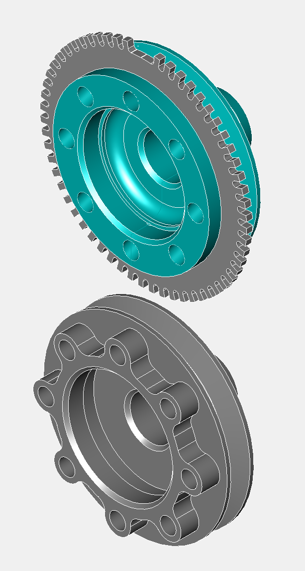
Panhard electronic ignition prototypes
Tuesday 02 July 2002
I soon made an adaptor to take the standard 2CV unit, as well as a new driveshaft complete with magnets, body shown below.
There was a big problem with this set up, and that was the rotation was the wrong way, which was a stumbling block for 123 at the time too. Fortunately I realised if I flipped the board the magnetic field would pass through the circuit board and the rotation would be effectively reversed, so I made a new model to test the idea, which was just a spacer sandwiched between the two previous halves.
So the board and magnets were in the base not the lid as with the 2CV set up, and as the 123 lid wasn’t needed, and I had to put a bearing in the top, to stop the wobble, I ended up with a rather large lump overall.
It wasn’t really surprising it ended up so large, but whereas I was making a conversion unit for the 123ignition before, I now had an opportunity to explore other options.
So having tested the set up made a spark, using my motorised ignition rig, I made a new prototype, that ended being another version a couple of days later, but at least it was getting smaller. I incorporated the original vacuum advance into this version too, but the biggest drawback was I would have to up the ante to fit the rev counter drive. I wasn’t able to cut a gear drive and the economics were such that it wash’t affordable to continue as it couldn’t meet the target price.
Still it was starting to look a lot more designed, and this is were I left off about 9 years ago.
