Panhard Ignition Improvements
Tuesday 04 June 2013 Filed in: Panhard Ignition
I have discussed the oil modifications in some detail over the years, but the next big area of improvement is the ignition.
The Panhard ignition was a distributor based system, that used a rotor arm to give a cylinder 1, cylinder 2 sequential output. There were two types of distributor fitted, vacuum only, and centrifugal & vacuum, but whatever type it is nowadays, the distributor will almost certainly be worn. I first noticed this in Ron Tyrrell’s car when I reversed the vacuum canister on his distributor to improve the running. Later I made a 123 ignition prototype distributor, but a board failure stopped the project.
It is quite common for this to be replaced with a Citroen 2CV coil, triggered by the points to create a wasted spark system, where cylinder 1 & 2 “fire” together, but the strongest spark is biased towards the cylinder with the most compression, which is full of the fuel air mix.
Other systems have been devised over the years of production, Hampe fitted twin contact breakers for twin plugging (although this was a wasted system for reliability), and some DB racers had a cam based triggering system from a special front cover. I found this out at Almen from Joel Brunel.
Whilst I was in Belgium, I got first hand knowledge of the distributor wear problem, when I was watching Stefaan timing up a MEP racer. This is basically a Tigre Panhard engine with a slightly different carburettor and manifold, but the distributor was a Ducellier vacuum & centrifugal type. He was running up the engine, setting the static advance based on the flywheel position, and getting a sluggish engine. In the end after disconnecting the vacuum, and measuring the centrifugal advance it was close on 28º and sticking, the vacuum was 23º, and static was an additional 21-31º. All these values are added together, so you could get close to 75º advance if you followed the manual.
Maximum advance for a Panhard engined racing sidecar running twin Amal carburettors was close on 32º, using high octane fuel, but burning modern pump fuel, the cars need a lot less than OEM. In fact, driving Sonia’s car & Brian’s whilst it was running, my static was around 10º to give nice off the throttle response, but at higher rpms, it could do with even less. Ron Tyrrell’s car has a manual advance and retard cable, a bit like a choke cable, which allows for variations to be made when running, and you do have to use it to make the engine more responsive under load. All of this tells you that the original Panhard ignition advance curve is not matched to present day fuels.
How would you go about to change this?
The obvious approach is modify the distributor, and Peter Breed does this, with a very nice 123 derived system. I actually did this years earlier, but the circuit board was too big, and so I had to make a new distributor casing. A distributor based system is still a good solution for some people, but it lacks accuracy, so modern cars use a more direct approach, mainly because of emissions, and the need to control things better.
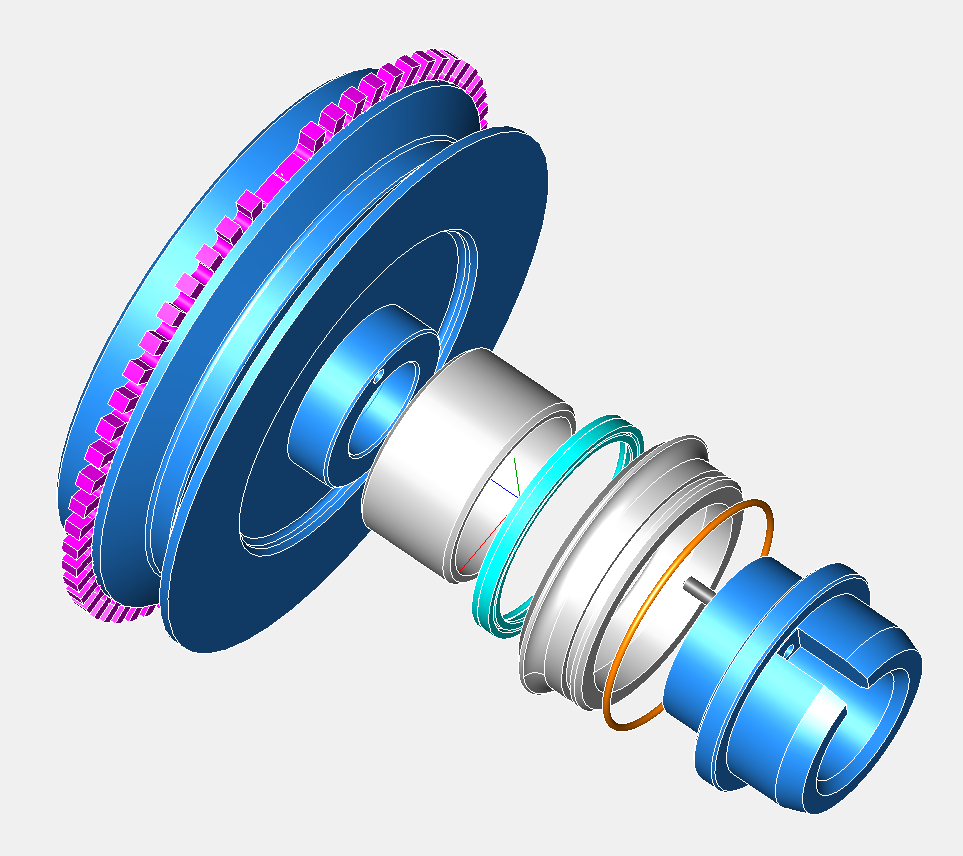
Some earlier cars used a crankshaft sensor, using either the flywheel, a front pulley or a crankshaft web, and wasted spark coils. I did look at flywheel sensing for the Panhard engine, and it was the need to develop an easy to fit kit that negated this, so this is why I went down the modified pulley route, as shown below.
If you look at the components required to make an easy to fit kit, the cost is starting to go far too high, so I had to come up with a better idea. The biggest single flaw, was the lack of camshaft position sensing, which meant another set up to do this. On modern cars with overhead camshafts, it’s relatively easy to sense the cam lobe via a hole in the camshaft cover or a trigger wheel on the camshaft belt drive pulley, but on a Panhard pushrod engine, things are at first a little more complicated, as there doesn’t seem to be a suitable position to place one on the cylinder. It was only after I exhausted the camshaft sensor location possibilities, that I decided a trigger off the camshaft timing gear would be best and least expensive way to modify the ignition on these cars, because it would need only one part to be modified.
Camshaft triggering is often combined with crankshaft or flywheel triggering to make a higher level of precision on multi cylinder cars or motorcycles, and often this is used to create sequential information, so now the engine management knows what stroke the cylinder is on, which just replicates what the distributor cap and contact breaker system did originally. However, when you look at the spark events, you can use a simpler camshaft trigger will suffice, as the Panhard engine is unlikely to exceed 6500 rpm, and it only has two cylinder to ignite. It could even be modified further to provide more accurate rotational information, by fitting a toothed wheel, so it became a “no brainer” to not take this further.
However, I needed to identify the easiest area to locate a sensor and trigger, and it soon became apparent, that although I could modify the existing pressed metal timing gear cover, it would be a struggle for most people. After a large amount of CAD work, and experimenting with different sensor types, a new timing cover was developed, and this also includes a new front seal detail, but only after an easy mod to the front pulley. This new part creates an accurate highly reliable triggering system, but it does require the fitting of the aluminium camshaft gear aka “alu pignon”, as well as fitting a steel inner ring to the front pulley. It is a big step forward in modernising the engines, without detracting from their originality, and allows them to run better with modern fuels.
The latest version is here…this is designed for a MicroSquirt or Imfsoft Master Mini 3TCI
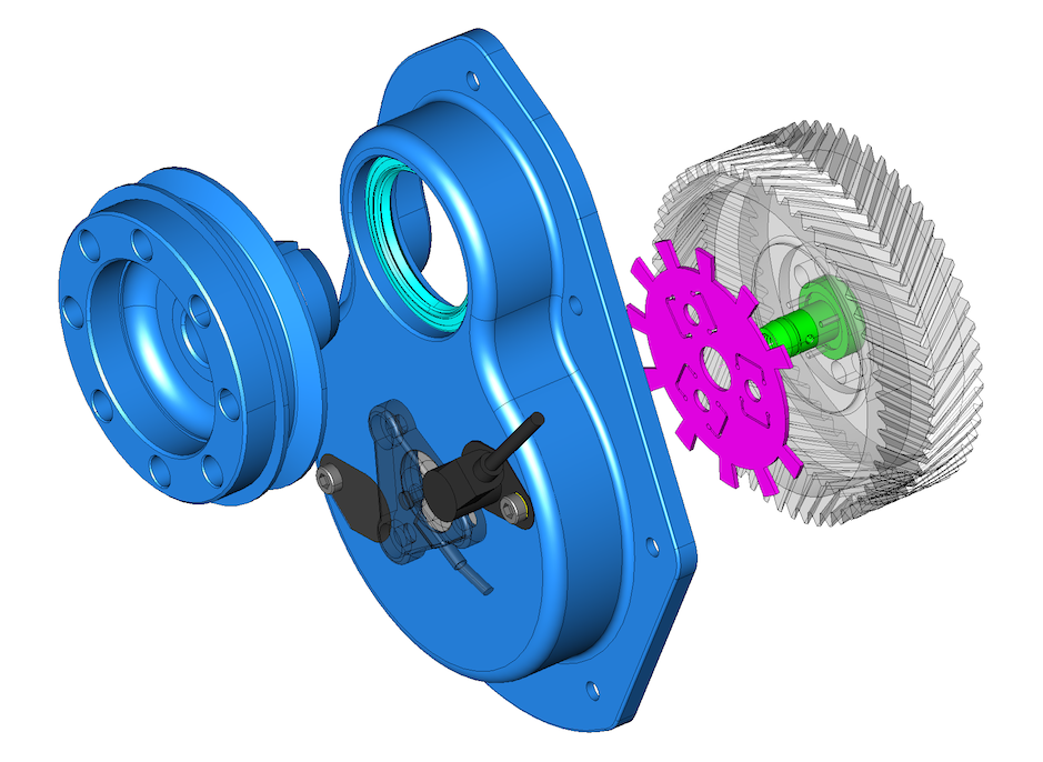
The part uses liquid gasket to seal the timing cover to the crankcase, and the original oil slinger parts, that diverted the oil from the piston ring oil seal are not required, a small laser cut spacer is used instead. The front crankshaft oil seal has an outer diameter of 65mm, which allows for a large variance in inner ring sizes to be used on the front pulley, as some Panhardistes have made modifications to this area already.
I recommend a 50 x 65 x 8 Viton oil seal, and a IR 45 x 50 x 15 inner ring.
The Panhard ignition was a distributor based system, that used a rotor arm to give a cylinder 1, cylinder 2 sequential output. There were two types of distributor fitted, vacuum only, and centrifugal & vacuum, but whatever type it is nowadays, the distributor will almost certainly be worn. I first noticed this in Ron Tyrrell’s car when I reversed the vacuum canister on his distributor to improve the running. Later I made a 123 ignition prototype distributor, but a board failure stopped the project.
It is quite common for this to be replaced with a Citroen 2CV coil, triggered by the points to create a wasted spark system, where cylinder 1 & 2 “fire” together, but the strongest spark is biased towards the cylinder with the most compression, which is full of the fuel air mix.
Other systems have been devised over the years of production, Hampe fitted twin contact breakers for twin plugging (although this was a wasted system for reliability), and some DB racers had a cam based triggering system from a special front cover. I found this out at Almen from Joel Brunel.
Whilst I was in Belgium, I got first hand knowledge of the distributor wear problem, when I was watching Stefaan timing up a MEP racer. This is basically a Tigre Panhard engine with a slightly different carburettor and manifold, but the distributor was a Ducellier vacuum & centrifugal type. He was running up the engine, setting the static advance based on the flywheel position, and getting a sluggish engine. In the end after disconnecting the vacuum, and measuring the centrifugal advance it was close on 28º and sticking, the vacuum was 23º, and static was an additional 21-31º. All these values are added together, so you could get close to 75º advance if you followed the manual.
Maximum advance for a Panhard engined racing sidecar running twin Amal carburettors was close on 32º, using high octane fuel, but burning modern pump fuel, the cars need a lot less than OEM. In fact, driving Sonia’s car & Brian’s whilst it was running, my static was around 10º to give nice off the throttle response, but at higher rpms, it could do with even less. Ron Tyrrell’s car has a manual advance and retard cable, a bit like a choke cable, which allows for variations to be made when running, and you do have to use it to make the engine more responsive under load. All of this tells you that the original Panhard ignition advance curve is not matched to present day fuels.
How would you go about to change this?
The obvious approach is modify the distributor, and Peter Breed does this, with a very nice 123 derived system. I actually did this years earlier, but the circuit board was too big, and so I had to make a new distributor casing. A distributor based system is still a good solution for some people, but it lacks accuracy, so modern cars use a more direct approach, mainly because of emissions, and the need to control things better.
Some earlier cars used a crankshaft sensor, using either the flywheel, a front pulley or a crankshaft web, and wasted spark coils. I did look at flywheel sensing for the Panhard engine, and it was the need to develop an easy to fit kit that negated this, so this is why I went down the modified pulley route, as shown below.
If you look at the components required to make an easy to fit kit, the cost is starting to go far too high, so I had to come up with a better idea. The biggest single flaw, was the lack of camshaft position sensing, which meant another set up to do this. On modern cars with overhead camshafts, it’s relatively easy to sense the cam lobe via a hole in the camshaft cover or a trigger wheel on the camshaft belt drive pulley, but on a Panhard pushrod engine, things are at first a little more complicated, as there doesn’t seem to be a suitable position to place one on the cylinder. It was only after I exhausted the camshaft sensor location possibilities, that I decided a trigger off the camshaft timing gear would be best and least expensive way to modify the ignition on these cars, because it would need only one part to be modified.
Camshaft triggering is often combined with crankshaft or flywheel triggering to make a higher level of precision on multi cylinder cars or motorcycles, and often this is used to create sequential information, so now the engine management knows what stroke the cylinder is on, which just replicates what the distributor cap and contact breaker system did originally. However, when you look at the spark events, you can use a simpler camshaft trigger will suffice, as the Panhard engine is unlikely to exceed 6500 rpm, and it only has two cylinder to ignite. It could even be modified further to provide more accurate rotational information, by fitting a toothed wheel, so it became a “no brainer” to not take this further.
However, I needed to identify the easiest area to locate a sensor and trigger, and it soon became apparent, that although I could modify the existing pressed metal timing gear cover, it would be a struggle for most people. After a large amount of CAD work, and experimenting with different sensor types, a new timing cover was developed, and this also includes a new front seal detail, but only after an easy mod to the front pulley. This new part creates an accurate highly reliable triggering system, but it does require the fitting of the aluminium camshaft gear aka “alu pignon”, as well as fitting a steel inner ring to the front pulley. It is a big step forward in modernising the engines, without detracting from their originality, and allows them to run better with modern fuels.
The latest version is here…this is designed for a MicroSquirt or Imfsoft Master Mini 3TCI
The part uses liquid gasket to seal the timing cover to the crankcase, and the original oil slinger parts, that diverted the oil from the piston ring oil seal are not required, a small laser cut spacer is used instead. The front crankshaft oil seal has an outer diameter of 65mm, which allows for a large variance in inner ring sizes to be used on the front pulley, as some Panhardistes have made modifications to this area already.
I recommend a 50 x 65 x 8 Viton oil seal, and a IR 45 x 50 x 15 inner ring.
blog comments powered by Disqus
