FINAL TEMPERATURE SENSOR ADAPTOR
27 June 2015
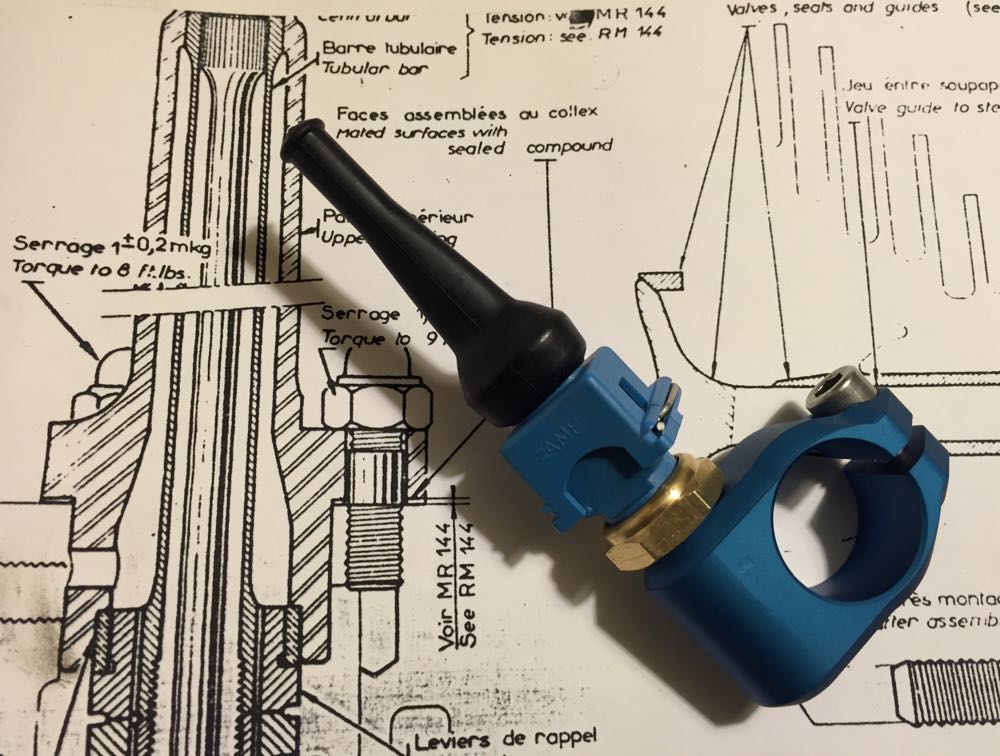
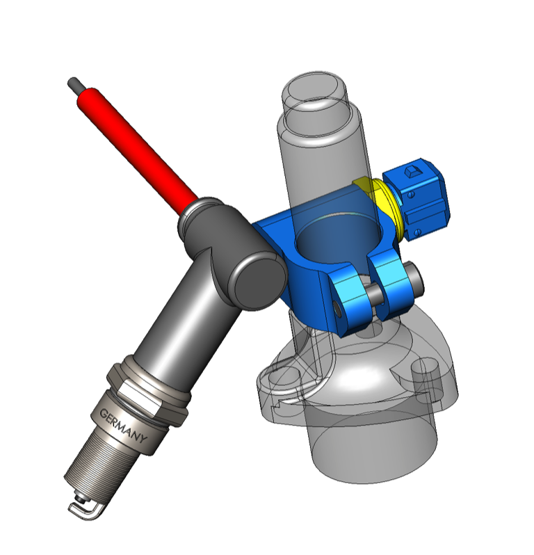
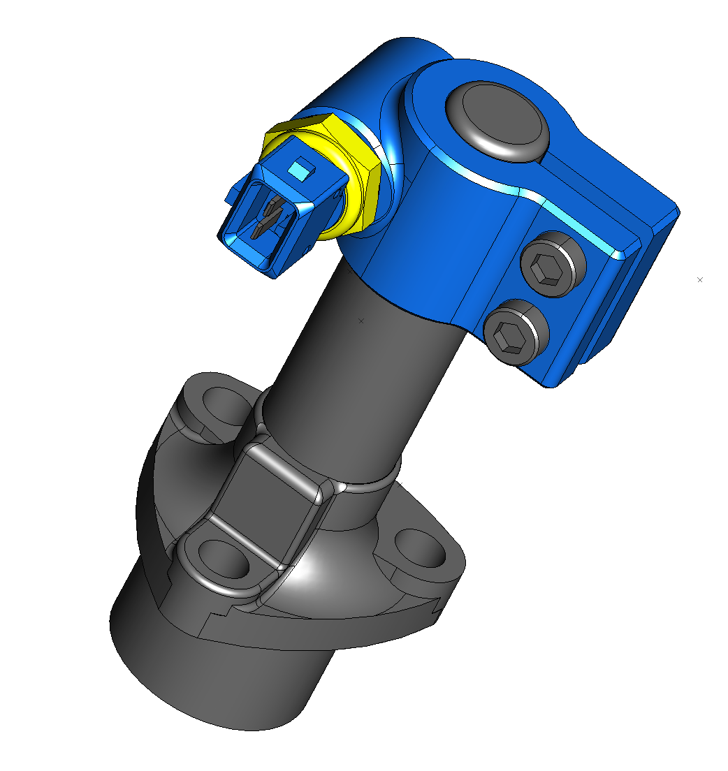
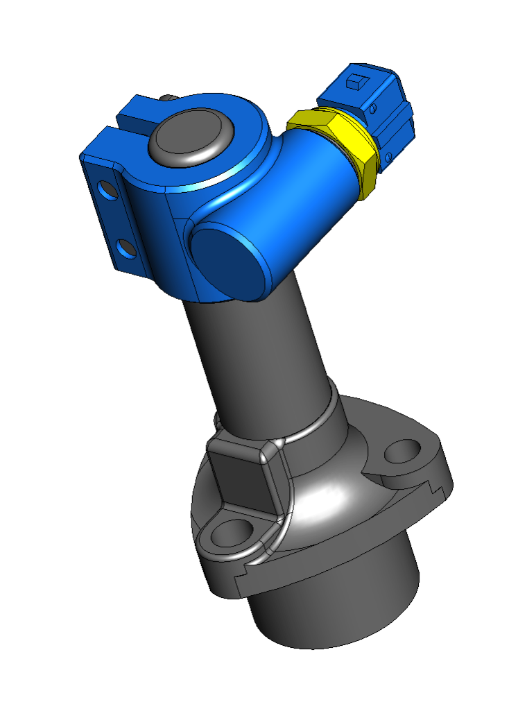
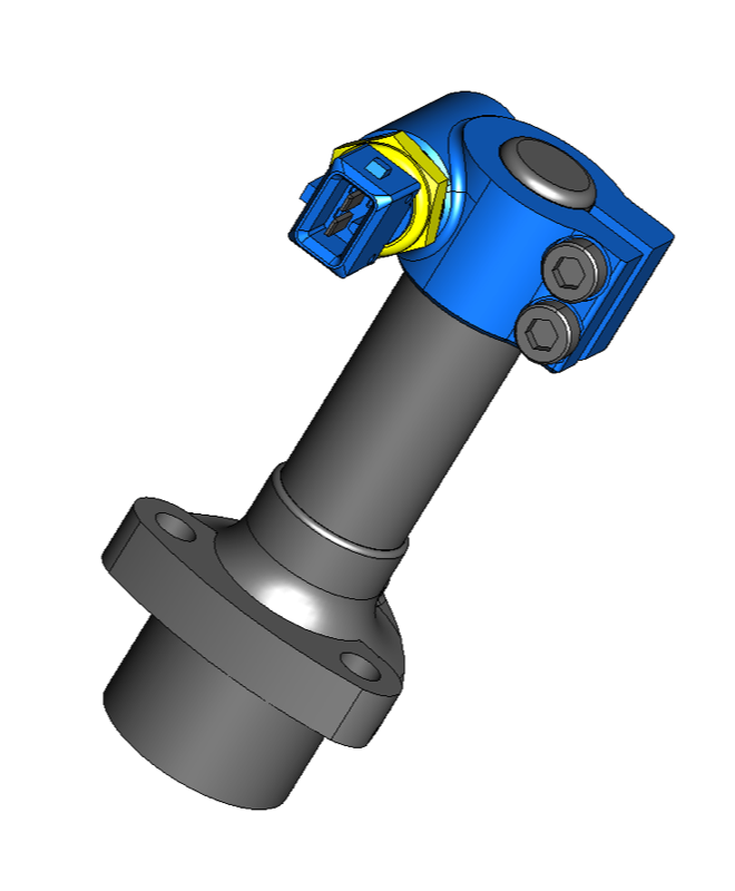
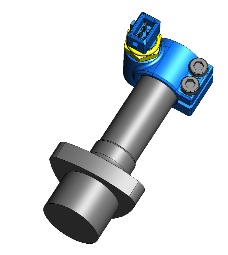
Finally got these parts anodised, and here’s a test fit, with temperature sensor and matching colour coded Junior Timer two pin connector.
CNC TEMPERATURE SENSOR ADAPTOR
11 October 2014
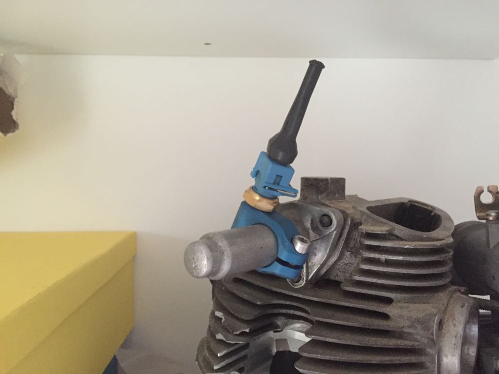
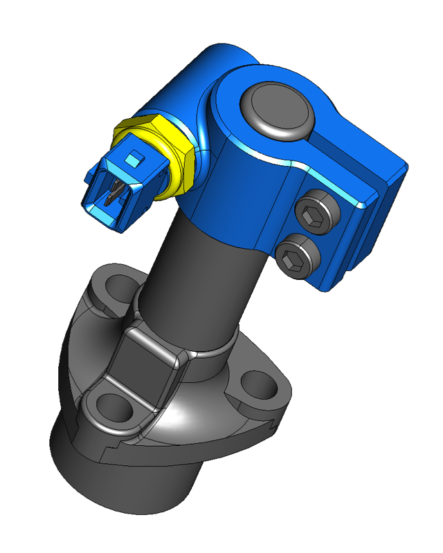
The CNC guys finally finished the temperature sensor adaptors, and they just need anodising now. They seem to fit both types of rocker tubes OK
UPDATED TEMPERATURE SENSOR ADAPTOR
04 October 2014
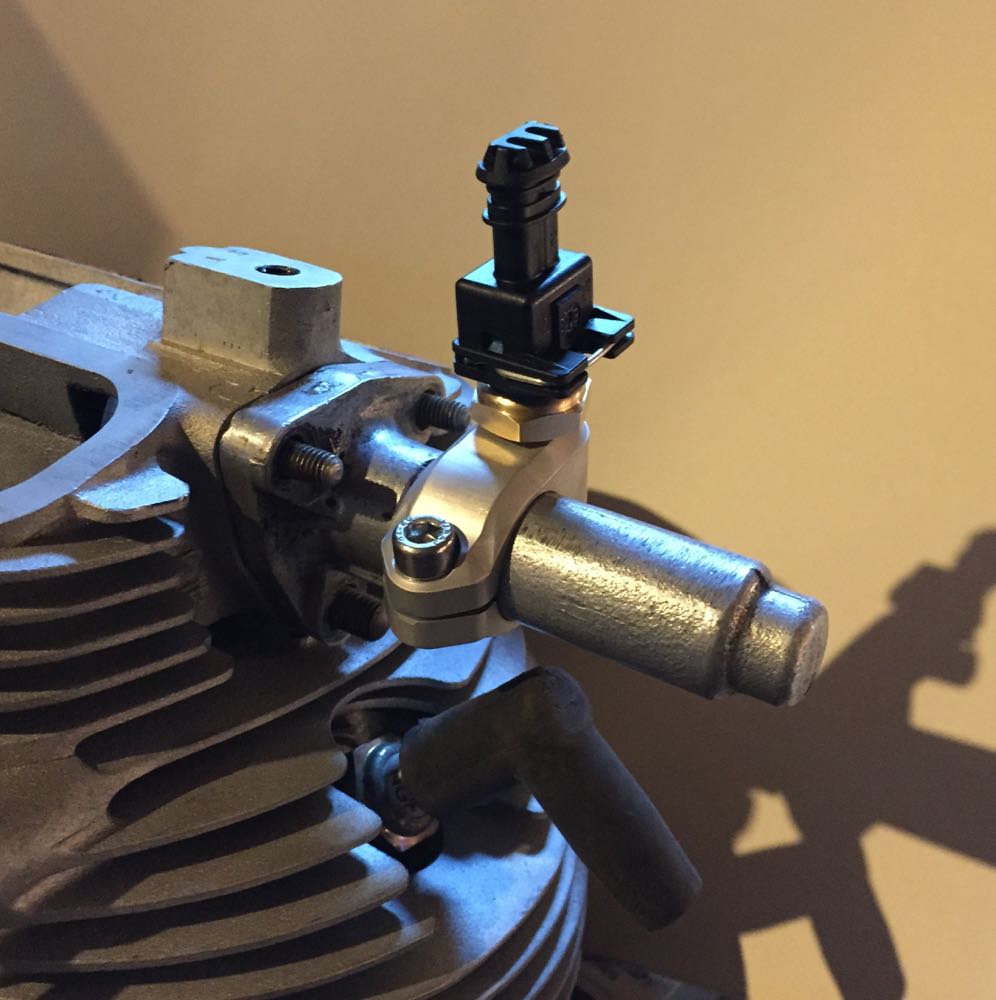
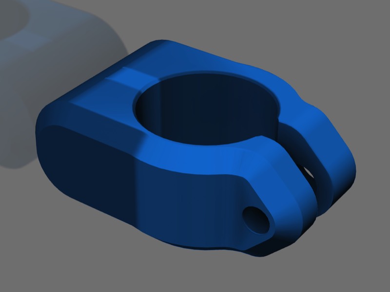
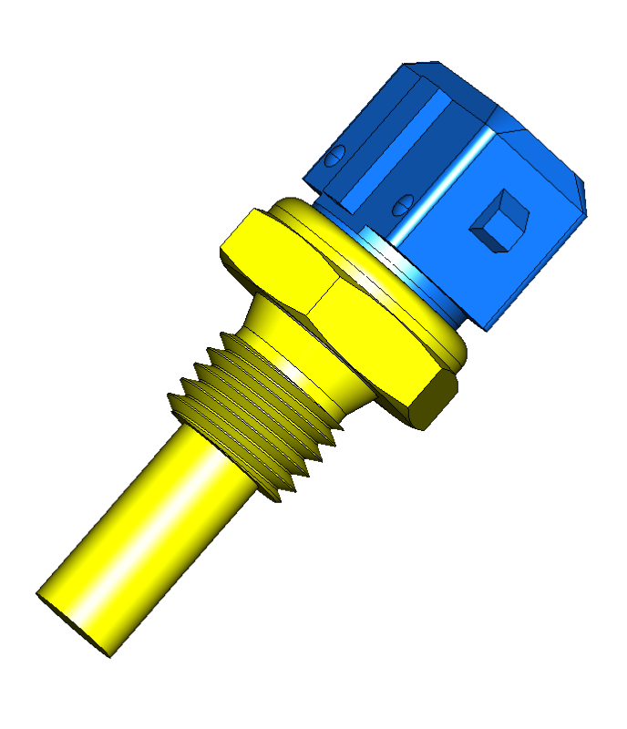
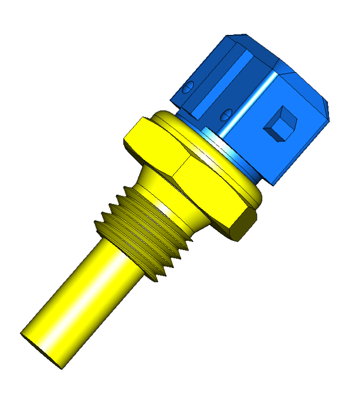
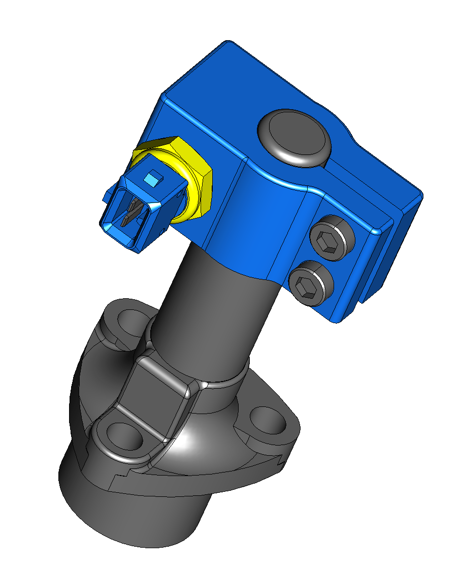
The CNC guy forgot to order the billet stock, so I could change the design...yet again...and I've introduced a little more clearance between the plug cap, and the adaptor, as you can see in this picture below.
It's only a small change, but it'll allow for the adaptor to be rotated, plus if you use a bulkier plug cap like a Champion one, then there will be more clearance. I prefer the NGK LB05EMH rubberised waterproof racing caps myself,


NEW TEMPERATURE SENSOR ADAPTORS
20 September 2014
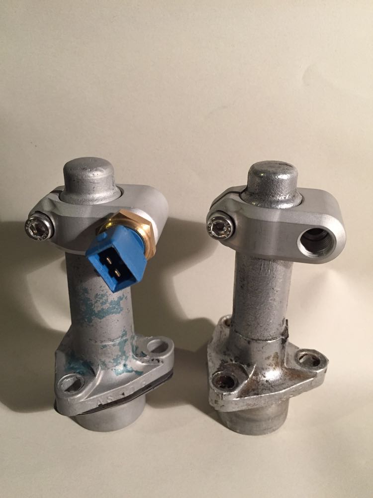
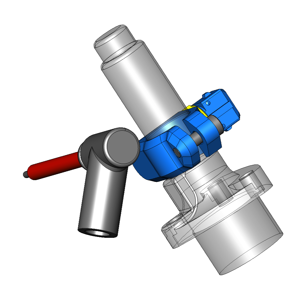
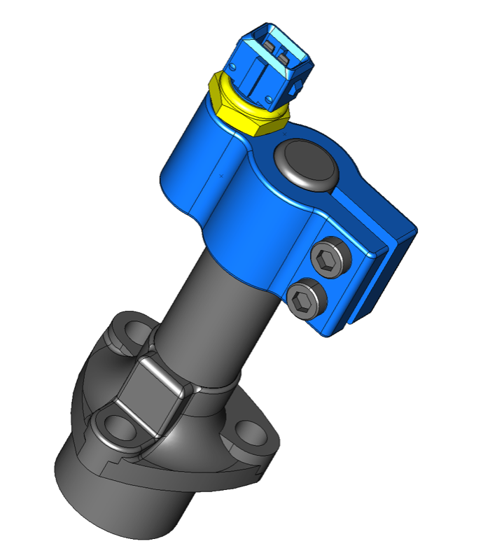
The CNC guy has got the billet in stock now, so this is the latest model (blue) I sent him. The temperature sensor adaptor now clamps lower down, so that there is more room for the spark plug, and after Belgium, trying to remove a plug from a hot cylinder convinced me not to put a larger lump of metal near your fingers, 'cos it's very hot , about 170ºC max.
CAD model of spark plug lifted from GrabCAD, I shall do my own later! :)

NEW TEMPERATURE SENSOR ADAPTORS
5 September 2014
I had a temperature sensor drop through the postbox the other day, all part of the engine temperature sensing for the ignition & injection projects.
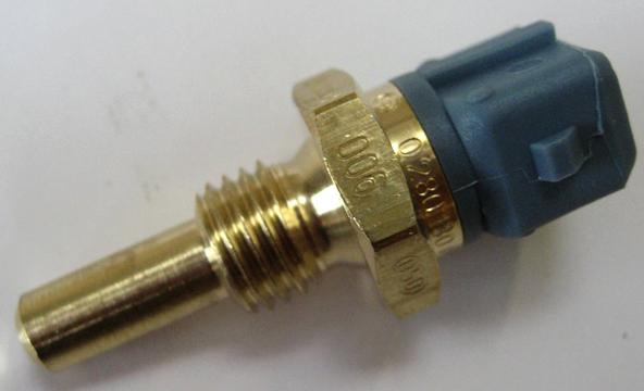
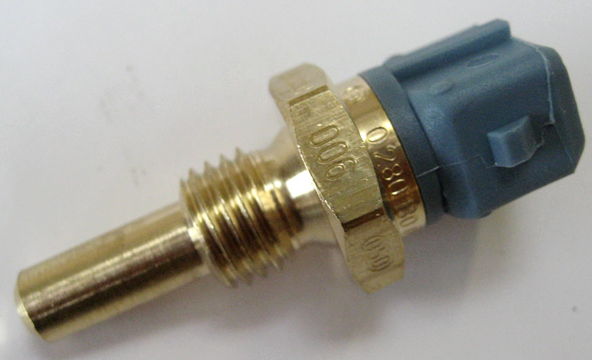
It is a robust low cost unit, so I modelled it in CAD, as I couldn't get a full 3D model online.
Here are a couple of my first thoughts, but will have to decide once the costs come in. I was influenced in using the torsion bar cover, as a French man aka Zenair had fuel injected a Panhard engine, and put it in his modified Z1. Here's a pictorial link to his sensor fitment, but I think he modded the torsion bar cover, something I didn't want to do. The basic premise is to keep it simple, and make it easy for others to follow.
I did an inline version (like Zenair's) as well as a 90º version, which is slightly more compact.
If anybody has a preference drop me a line, or better still if you'd like one let me know.
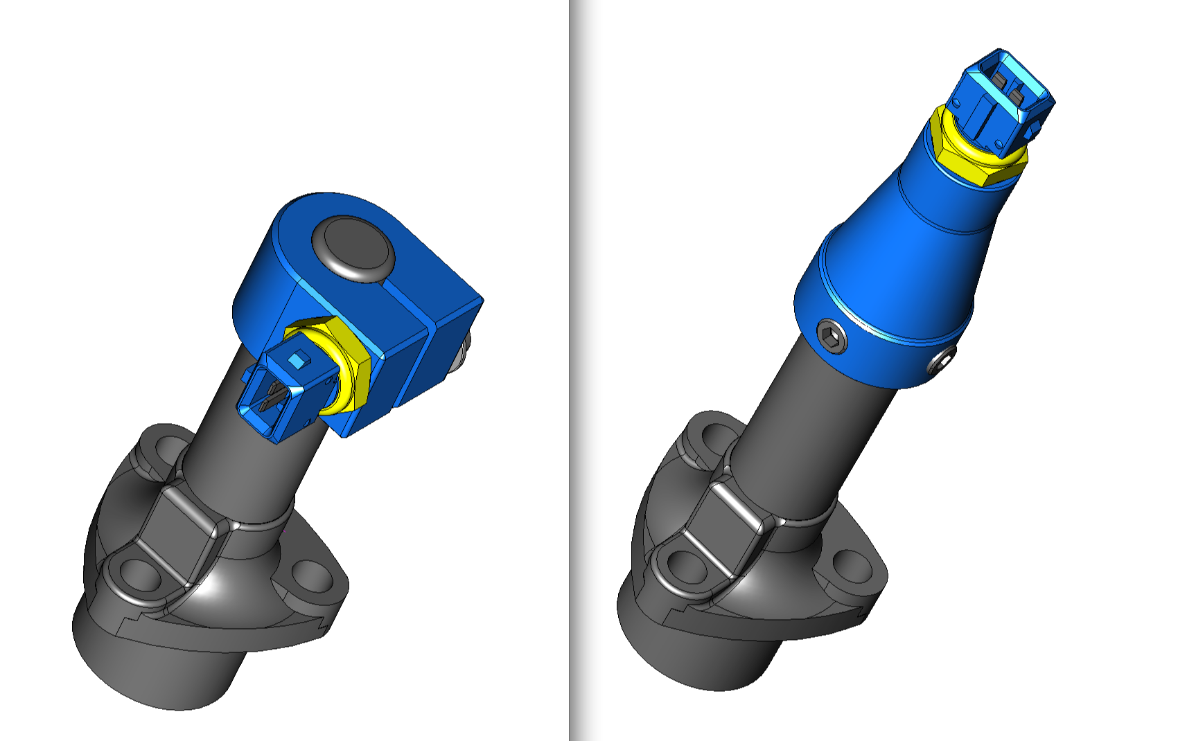

Neither of the above went on to win, as I think the right hand image above is the winner in terms of machine time.
Quite like the first image below for its honest functionality, but the second one below this, has all the stepped drillings from one side, so that can be done in two not three operations, but it does look a little heavier, and cobby sitting on the torsion bar tube like that. :(

Trying to reduce the CNC setting has definitely disturbed the aesthetics... getting tired now, time for a cup of tea or a sleep.

So no sleep, and the the tea was nicely chilled by the time I tweaked this model above, but I am really impressed with SharkFX, and the bolt head tutorial for ViaCAD, as I was doing it a different way.
This is what's going to the CNC shop, unless I get some grumbling from Panhardistes across La Manche or I dither.

There were a few inconsistencies in the model, so after a dither it was tweaked yet again, and it's now a little better for it. Not that many people will notice, or probably want one, hobbies like this are very personal. At least it'll be easy to fit, relatively low cost and generic enough to cover all the options.
It was an interesting exercise for me, as this was a "no paper was used in designing this component just electrons". Normally, I'd sketch something up first, which isn't a bad idea, as going straight to CAD is very hard focussed, and can limit your lateral thinking soft focus phase.

A little bit of feedback suggests that the spark plug access might be compromised, and after looking at my cylinder by the computer desk, I thought I could make the adaptor a little smaller. Another comment was the torsion bar covers vary in size slightly, so I've tweaked the mating surfaces to suit, and offset the screws to tighten on a conical surface.
More doodles...shorter clamp overhang at first, then less height and stubbier too. Latest at the bottom.

Hopefully this is the basis of the first test pieces now, and while I am waiting, I must clean my stock of test cylinders up, and do a dummy fit.

NEW IGNITION MODULE (Imfsoft Direct TCI discontinued)
19 July 2014
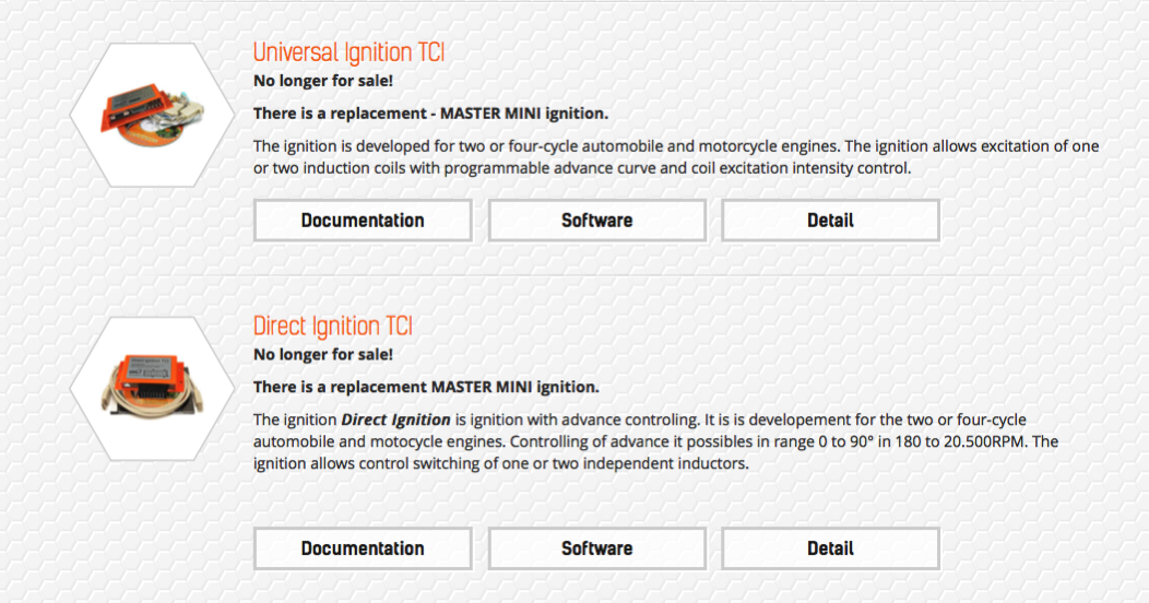
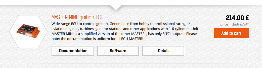
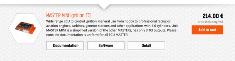
I have just found out the Ignition TCI that the original timing cover conversion was made for is no longer available. It was €178,00, but has been replaced by a new model called the MASTER Mini Ignition TCI, which costs €214,00 now, but uses different software, and has an addition driver circuit., which means it can control 3 outputs.

NEW OIL LIGHT PISTON (Update)
18 April 2014
I have modified the oil light piston, as part of my 2012 engine rethink.
This new oil light piston is slightly different in principle, and is part of the oil pump refinements I have been planning for some time. The original oil pump, contrary to what you hear is actually more than adequate for fast road engines, it's the total oil capacity and flow rate that is suspect. In order to extract more efficiency into the lubrication system, rather than drop the excess oil pressure into the sump, I am going to use the oil light piston as the oil pressure relief valve. This means that the priority is to maintain oil pressure into the camshaft gallery, which also feeds the crankshaft bearings.
I already revert the engines back to the earlier oil distribution system, as this balances the oil flows to the front and rear bearings, which is something the later engines didn't do. The other inefficiency is the size of the pick up pipe in the oil pump base. It is deliberately constricted to reduce the flow, and simply opening this up, will reap better pressure and flow the original set up.
In fact my filter set up from years ago benefitted from this, but the capacity of the sump wasn't increased, so at times the oil pressure light fluctuated, yet the cylinder head flows were unaffected.
Anyway, fast forward to present day, and with a little rethink the whole concept is elegantly updated.
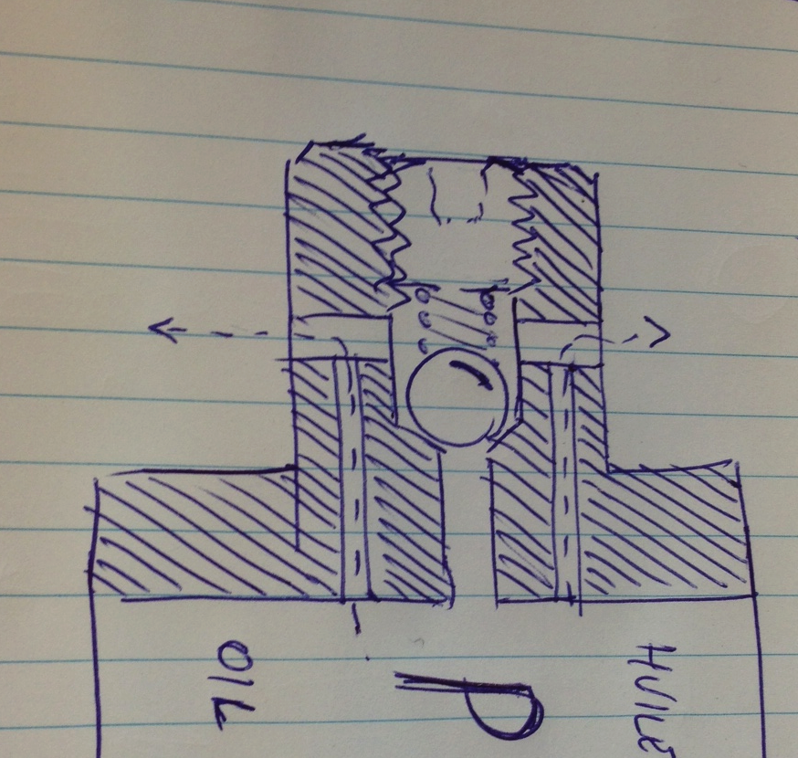

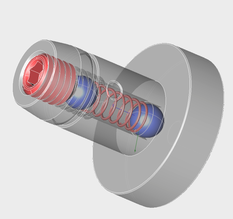
So the large hole is for the oil pressure relief function, and the small hole is to lubricate the timing gear. If you look at the earlier set up, and equate the hole diameters with the angular timing, it actually equates to a sub Ø1,00 mm hole all the time. The oil pressure relief valve function also lubricates the gear, more so when cold or at high revs, but as I make oil holes in the timing gear cavity to return the oil to the sump, there is no issue with excessive churning of the oil, because the oil level is kept low.
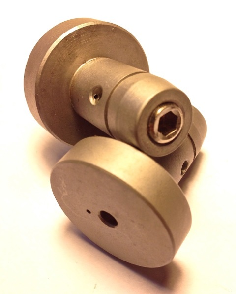
Here's a view of the finished part, but the adjusting screw for the oil relief pressure blow off hasn't been set yet. It is below the surface when finally set.

NEW PULLEY FOR ALUMINIUM COVER (Update)
18 February 2014
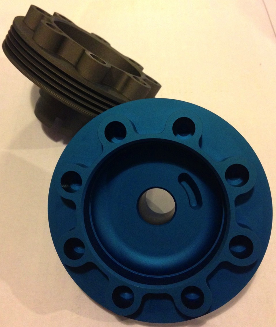
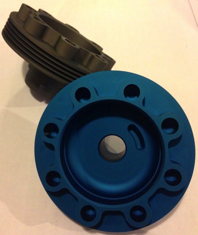
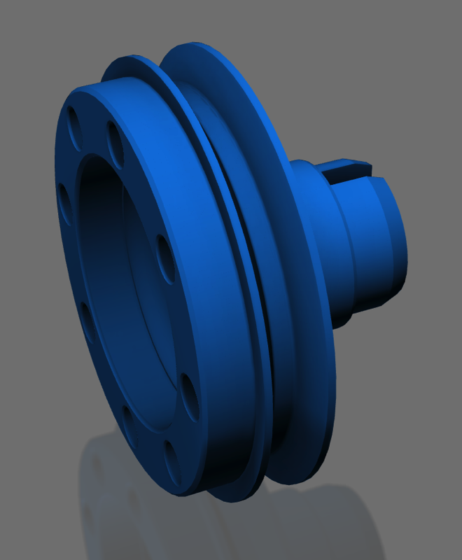
The small batch of pulleys that were completed last week, have been sent to the anodisers and they are finally finished.
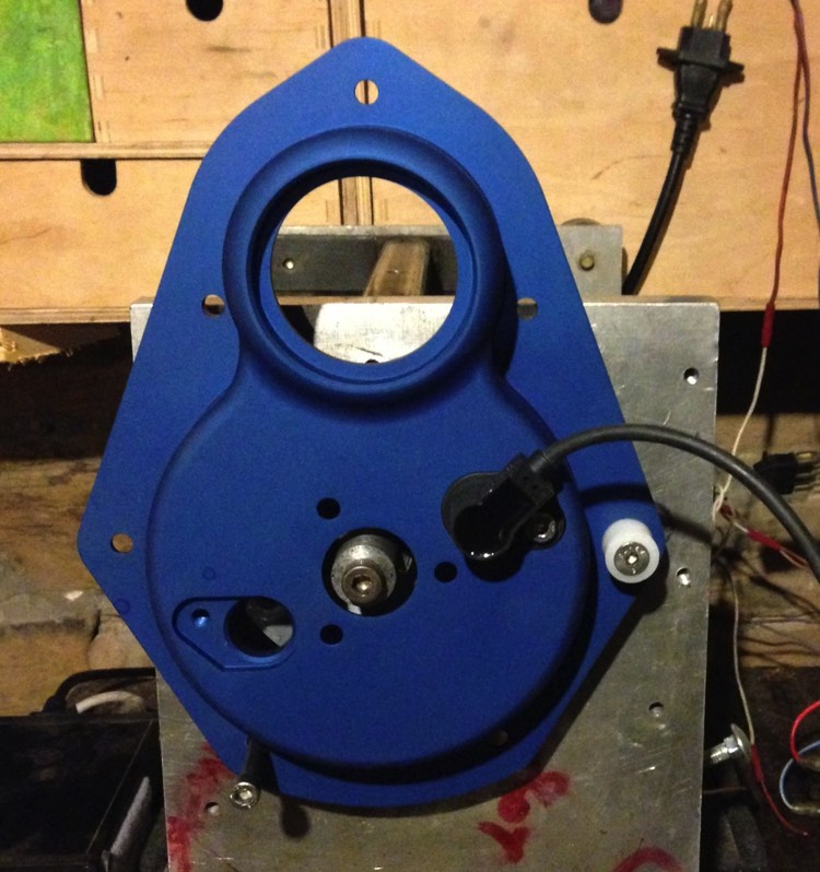
This new pulley takes a standard inner ring sleeve, and allows for a simpler installation without having to re-machine the old pulley in a lathe. There is also an option for a 4PK poly vee belt conversion, which allows a modern alternator, like those found on small Peugeot & Citroen cars, as well as some Japanese cars (picture below).
The only colour option is blue, the grey one is a development model with adjustable spring tension to allow the turbine to slip.
18 February 2014
The small batch of pulleys that were completed last week, have been sent to the anodisers and they are finally finished.
This new pulley takes a standard inner ring sleeve, and allows for a simpler installation without having to re-machine the old pulley in a lathe. There is also an option for a 4PK poly vee belt conversion, which allows a modern alternator, like those found on small Peugeot & Citroen cars, as well as some Japanese cars (picture below).
The only colour option is blue, the grey one is a development model with adjustable spring tension to allow the turbine to slip.
TRIGGER WHEEL MODIFICATIONS (Update)
2 January 2014
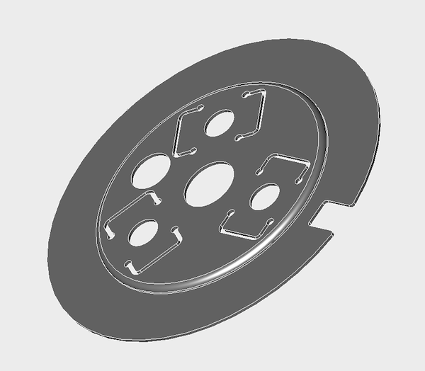
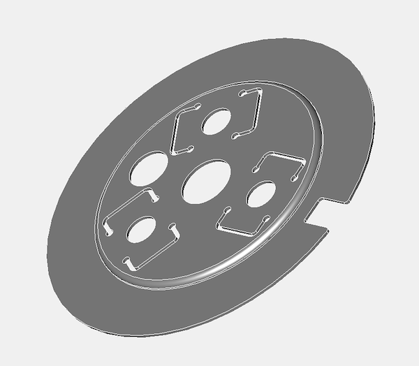
The laser cutters are back from there Christmas and New Year holidays, so I sent a new drawing over. This is the second generation version of the earlier trigger, and it will form the basis of the next batch of tests.
This new trigger wheel system allows for a simpler installation, and reduces errors in calibration.
2 January 2014
The laser cutters are back from there Christmas and New Year holidays, so I sent a new drawing over. This is the second generation version of the earlier trigger, and it will form the basis of the next batch of tests.
This new trigger wheel system allows for a simpler installation, and reduces errors in calibration.
So far the Imfsoft ignition & the MicroSquirts are working OK on the test rig, and both are using a single trigger and two sensors input system. The Imfsoft is able to handle the raw inputs from pin 2 of the Opel sensor, but the Microsquirts all need pull ups to make them work. The MicroSquirts are in theory able to use either MSExtra "Twin Trigger" mode, or MSII B&G "Dual Spark" in "Dual Inputs, Timing from 1 cam tooth" mode. Unfortunately the fuelling capabilities of the MSExtra variant is flawed, so I have stopped working on this, but the B&G code is working very well, and as expected, detecting cranking RPM from 16 revs per minute, and is maintaining a stable trigger at 28000 rpm.
However, as the new trigger format has a lower profile, there can now be a M-N cam trigger wheel option for the two sensor timing cover (only one sensor will be required), meaning both firmware variants will be able to use this input system, and the fuelling and ignition will have a higher resolution.
TRIGGER WHEEL MODIFICATIONS
24 December 2013
It was always my intention to try and consolidate the timing cover models, and I had thought that the two sensor version with a simple trigger would work with the Imfsoft ignition and also the MicroSquirt* models. Although I can get them to work OK up to 10K on their own, when the ignition circuits are activated, so that's coils & spark plugs, I get sync errors, which is a noise related issue.
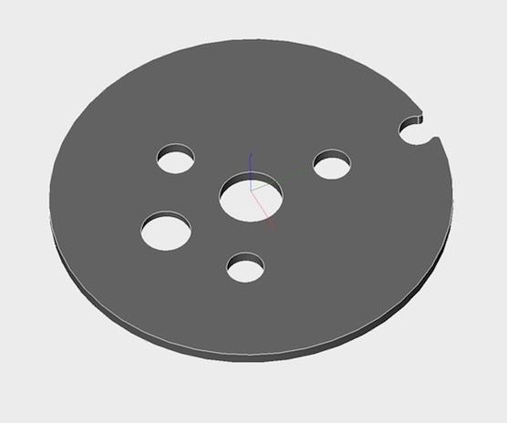
It turns out when I chose the Opel sensors I made work slightly harder for myself unwittingly, and the easy solution is to change the trigger from a simple raised lug (aka a set screw), to a metal disc with a hole in it. This will invert the signal trace, and guarantee more robustness as well.
It is a fundamental requirement of any electronic ignition or injection system to have robust triggering, and this development brought to my attention, by a fine French friend, will result in a simpler install for everybody too.
I have placed a sketch of the revised trigger wheel below.
*MicroSquirts are compact MegaSquirts, that run a dual spark set up as standard.
NEW EFI INSTALLATION
16 December 2013
I am not ready to go public on my new EFI project, but the basic inlet manifold mods are done. I am trying to acquire the right connectors, so in the meantime I am resurrecting the "engine test rig", seen in the picture above. Using a sample two hole sensor timing cover, I will first check the Imfsoft Direct Ignition unit is functioning on Brian's engine, and then switch to the MicroSquirt module and start testing the "dual spark" B&G firmware. The beauty of this is I can use the same trigger & sensor set up for both the Imfsoft ignition and the MicroSquirt injection, and this helps test the future proofing I had in mind when I first drew up the concept.
I am still waiting for my fuel system to come in the post, and when it does I shall be making the tools and parts I need to complete this part of the installation.
I have to say it's looking good at the moment, but ideally I really need an aluminium timing camshaft gear to convert my 24C engine
.
NEW VALVES COMING
13 December 2013
After the disappointed of Brian's two part valve letting go, the holy grail of finding an affordable valve has arrived.
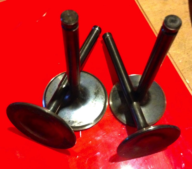
Totally unexpected and on Friday the 13th, I managed to finally acquire some valves that are a close match to the OEM stock.
Unfortunately, they are not from a production engine, so are a little pricier than expected, but they have wonderful specifications. 21/4N stainless, waisted stems, tipped and nitrided, plus they are so much lighter than OEM. I reckon the exhaust and inlets are 15% lighter before I regrind the keeper detail. Another added bonus is the inlet is 46mm, more than enough for a standard 850, and enough leeway for a 1000cc too.
NEW OIL LIGHT PISTON
14 September 2013
I have just gone public, on my latest oil lubrication refinements to the Panhard flat twin on the French Panhard forum, so I am making this page to explain the idea in more detail.
I made a revised oil light piston over 10 years ago, and in the earlier engines, that fed the oil for the front cylinder big end bearing through the crankcase drilling via the camshaft, it was possible to equalise the camshaft oil drillings, and make the oil flow & pressure more equal for each cylinder. This had a small hole and a pressure relief valve in it, that bled oil from the central camshaft oil gallery into the timing gear cavity when the oil was over 2 bar or 30 psi.
In my experiments with the oil filter conversion kit some years before this oil light piston, I noticed, I could improve the oil pumps performance by enlarging the oil pick up pipe, and flowing the oil pump output. One thing I did see was reduced cavitation, that's the presence of air bubbles and a reduced tendency for the oil pump bypass valve to open. In fact with warm 20W/50 oil, I could set the bypass valve to open at around 7 bar or 90psi before I got cavitation.
A Panhard engine doesn't need high pressures, except in three areas where it is beneficial, the camshaft, filling the slingers in the crankshaft and in the bronze bushes of the valve gear torsion bar springs. Unfortunately the bronze bushes are limited by the blow off pressure of the clapet just above the oil pump. there is a bypass that opens once the hydraulic valve adjusters are up to pressure.
For the other two areas, the camshaft and filling the slingers, it would be beneficial to raise the pressure slightly, but the most important bit is to equalise the oil delivery to the big end bearings, as more oil in this area will take heat away and reduce wear. If you equalise the delivery, the weakness in the front big end bearing will not happen.
Fast forward a few years, and I have now decided to replace the oil pump relief valve that dumps oil into the sump, and replace this with a new oil relief valve combined into the oil light piston. Why did I do this, partly to boost the oil supply to the timing gears over my previous solution, and also as a result of a conversation I had with Jean Paul Cesar, who is using higher oil pressures in his engine, and had a requirement to keep the pressure in the system higher.
By fitting the bypass valve here, all the oil pump output is used to good effect, and it's not dumping the oil back into the sump, before it's done any useful work.
It still goes back into the sump, but it lubricates the timing gears now, but only when it gets up to pressure. If you make the new drillings at the base of the timing gear cavity, it goes back into the sump anyway, and you lower the oil level of the gears, which is beneficial.
Boosting the oil pressure in the camshaft gallery enhances the performance of the plain bearing surfaces. If you have a later engine and modify the oil drillings, and also block off the side drilling that feeds the timing gears, then you are in a win win situation.
At the moment, I haven't decided on a bypass pressure, because I expect 4 bar at the oil pump, will be slightly less in the nose of the camshaft, if you want to maintain the original system pressure.
I can adjust the relief valve pressure fro the default 4 bar or higher, but you can only use the higher values if you modify the oil pump outlet, as shown… essentially you must radius the oil pump outlet and enlarge & centralise the feed into the crankcase, which reduces the back pressure and cavitation. So much so, the original oil pumps performance will be enhanced, possibly negating the trend to fit larger oil pumps, which seems to be the de facto solution for some. I prefer to increase the oil volume or capacity, by fitting an additional sump, but if you've visited this site before you know this by now.
Back on topic, I created a spreadsheet to do the calculations, which uses the same spring from my oil filter kits of yesteryear.
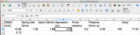
The “depression” value is the recess depth to the set screw from the tip of oil light piston, measured with verniers, so by screwing the set screw in you increase the distance and the higher the pressure the valve will open at, and obviously reducing the depth has the opposite effect.
14 September 2013
I have just gone public, on my latest oil lubrication refinements to the Panhard flat twin on the French Panhard forum, so I am making this page to explain the idea in more detail.
I made a revised oil light piston over 10 years ago, and in the earlier engines, that fed the oil for the front cylinder big end bearing through the crankcase drilling via the camshaft, it was possible to equalise the camshaft oil drillings, and make the oil flow & pressure more equal for each cylinder. This had a small hole and a pressure relief valve in it, that bled oil from the central camshaft oil gallery into the timing gear cavity when the oil was over 2 bar or 30 psi.
In my experiments with the oil filter conversion kit some years before this oil light piston, I noticed, I could improve the oil pumps performance by enlarging the oil pick up pipe, and flowing the oil pump output. One thing I did see was reduced cavitation, that's the presence of air bubbles and a reduced tendency for the oil pump bypass valve to open. In fact with warm 20W/50 oil, I could set the bypass valve to open at around 7 bar or 90psi before I got cavitation.
A Panhard engine doesn't need high pressures, except in three areas where it is beneficial, the camshaft, filling the slingers in the crankshaft and in the bronze bushes of the valve gear torsion bar springs. Unfortunately the bronze bushes are limited by the blow off pressure of the clapet just above the oil pump. there is a bypass that opens once the hydraulic valve adjusters are up to pressure.
For the other two areas, the camshaft and filling the slingers, it would be beneficial to raise the pressure slightly, but the most important bit is to equalise the oil delivery to the big end bearings, as more oil in this area will take heat away and reduce wear. If you equalise the delivery, the weakness in the front big end bearing will not happen.
Fast forward a few years, and I have now decided to replace the oil pump relief valve that dumps oil into the sump, and replace this with a new oil relief valve combined into the oil light piston. Why did I do this, partly to boost the oil supply to the timing gears over my previous solution, and also as a result of a conversation I had with Jean Paul Cesar, who is using higher oil pressures in his engine, and had a requirement to keep the pressure in the system higher.
By fitting the bypass valve here, all the oil pump output is used to good effect, and it's not dumping the oil back into the sump, before it's done any useful work.
It still goes back into the sump, but it lubricates the timing gears now, but only when it gets up to pressure. If you make the new drillings at the base of the timing gear cavity, it goes back into the sump anyway, and you lower the oil level of the gears, which is beneficial.
Boosting the oil pressure in the camshaft gallery enhances the performance of the plain bearing surfaces. If you have a later engine and modify the oil drillings, and also block off the side drilling that feeds the timing gears, then you are in a win win situation.
At the moment, I haven't decided on a bypass pressure, because I expect 4 bar at the oil pump, will be slightly less in the nose of the camshaft, if you want to maintain the original system pressure.
I can adjust the relief valve pressure fro the default 4 bar or higher, but you can only use the higher values if you modify the oil pump outlet, as shown… essentially you must radius the oil pump outlet and enlarge & centralise the feed into the crankcase, which reduces the back pressure and cavitation. So much so, the original oil pumps performance will be enhanced, possibly negating the trend to fit larger oil pumps, which seems to be the de facto solution for some. I prefer to increase the oil volume or capacity, by fitting an additional sump, but if you've visited this site before you know this by now.
Back on topic, I created a spreadsheet to do the calculations, which uses the same spring from my oil filter kits of yesteryear.
The “depression” value is the recess depth to the set screw from the tip of oil light piston, measured with verniers, so by screwing the set screw in you increase the distance and the higher the pressure the valve will open at, and obviously reducing the depth has the opposite effect.
NEW PULLEY FOR ALUMINIUM TIMING COVER
7 SEPTEMBER 2013
The new aluminium front timing cover is designed to take a modern double lipped oil seal, however the OEM front pulley isn't. This means it has to be machined to accept an inner ring, but it seems this is not so easy for the people out there to get done. So inline with the philosophy of not destroying OEM parts, I have made enquiries about making a new pulley to accept the inner ring as is. This has the added advantage of being truly concentric and means the front timing cover can be swapped out by anyone able to wield a few tools.
First thoughts in CAD below, which now includes the recess to take the balance weight lug.
CAMSHAFT TRIGGER WHEEL PROTOTYPE
14 AUGUST 2013
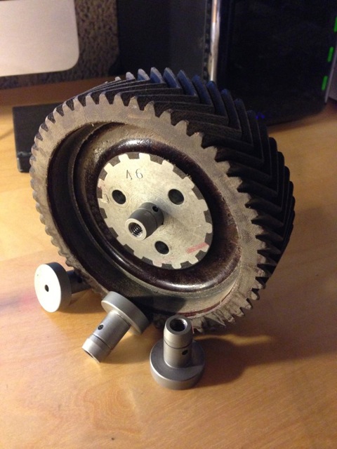
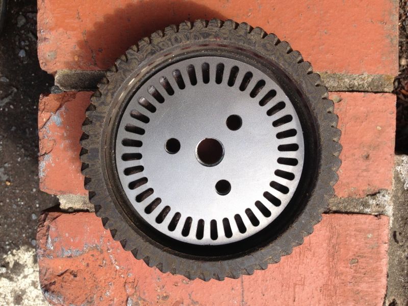
I am in the process at looking at some experimental trigger wheels to suit the new CNC timing cover, and these will fit within both types of camshaft gear, aluminium or Celeron.
These will be used by aftermarket engine management controllers, and it will have a 36-1 camshaft based trigger wheel configuration. It should only need one sensor and in the next few weeks I will complete the testing of the wheel, to make sure I get clean and precise triggering, at all expected t/min or rpms.
This was the first idea, but it was too expensive to machine, and because the Vauxhall & Opel crankshaft sensor is very sensitive and discriminates teeth patterns so well, I was able to look at other manufacturing processes.
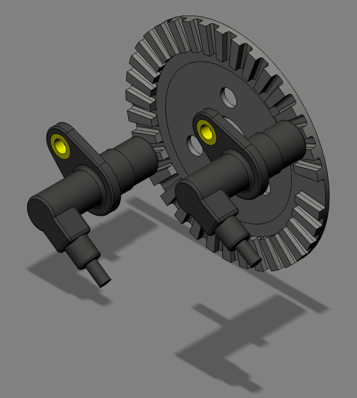
Here is a prototype version, that will be used in testing. I have another version, but this is the best and lowest cost part I can come up with. It will come with a black phosphate coating once successful testing has been completed.
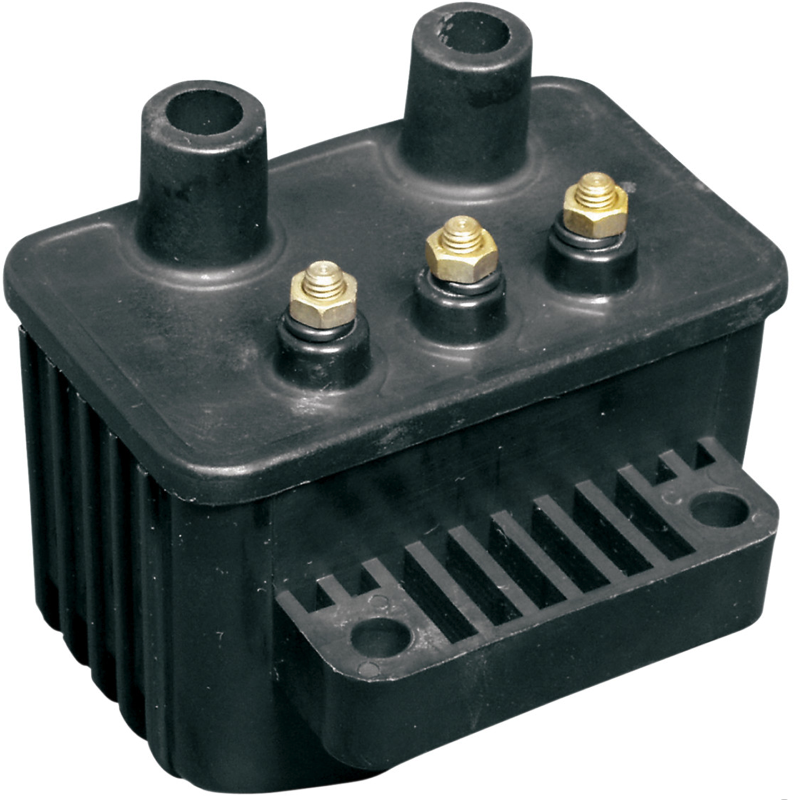
IGNITION COIL UPDATE
10 JUNE 2013
The Panhard ignition had a slight hiccup just before the RIP 2013 at Almen, and now I know why.
The Imsfoft IgnitionTCI 6.1 can only cope with coils with a resistance of 2.5 Ohms or more, and the Bosch Motorsport coils are much lower than this. I have now bought another make of Twin Single Fire coil, from a Harley Davidson aftermarket manufacturer, and the good news this is cheaper than the Beru equivalent I was planning to use and it is also makes for easier connectors and no ignition modules either. This will save even more money, and make the ignition kit even more affordable.
Interestingly, there are quite a few variants of Harley Davidson coils, even twin plugged cylinders and they have enough resistance to use in parallel if needed, and still not need ignition modules, which is rather promising.
I hope to test this over the next few days when the replacement Imfsoft Ignition comes in the post.
CAMSHAFT TRIGGER WHEEL PROTOTYPE
14 AUGUST 2013
I am in the process at looking at some experimental trigger wheels to suit the new CNC timing cover, and these will fit within both types of camshaft gear, aluminium or Celeron.
These will be used by aftermarket engine management controllers, and it will have a 36-1 camshaft based trigger wheel configuration. It should only need one sensor and in the next few weeks I will complete the testing of the wheel, to make sure I get clean and precise triggering, at all expected t/min or rpms.
This was the first idea, but it was too expensive to machine, and because the Vauxhall & Opel crankshaft sensor is very sensitive and discriminates teeth patterns so well, I was able to look at other manufacturing processes.
