Nov 2012
Panhard crankshaft truing
Sunday 04 November 2012 Filed in: Blog Comments
Too cold to work in the roof of the house first thing in the morning today, so for a few hours while it got warmer, I decided to make my crankshaft truing tool on the Elliot mill. I can’t do anything else until I collect the other liners and crankshafts, so it seemed fair to make a start on something else.
Several months ago, Martin McClarence had given me an ex Woody crankshaft to true up that had turned somehow.
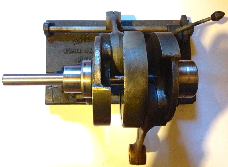
When he installed this low mileage crankshaft (10 miles) into his engine, it decided to let go a little and break the piston ring seal and damage the timing gear cover. I knew it was bent because Martin couldn’t fit the rear bearing plate in the crankcase, when the crankshaft was installed in the front bearing, and this was confirmed by the wobble I saw on the Alpha crank truing rig. It is very awkward to true one of these cranks on a traditional crankshaft rig, which is why making the special tool is so beneficial.
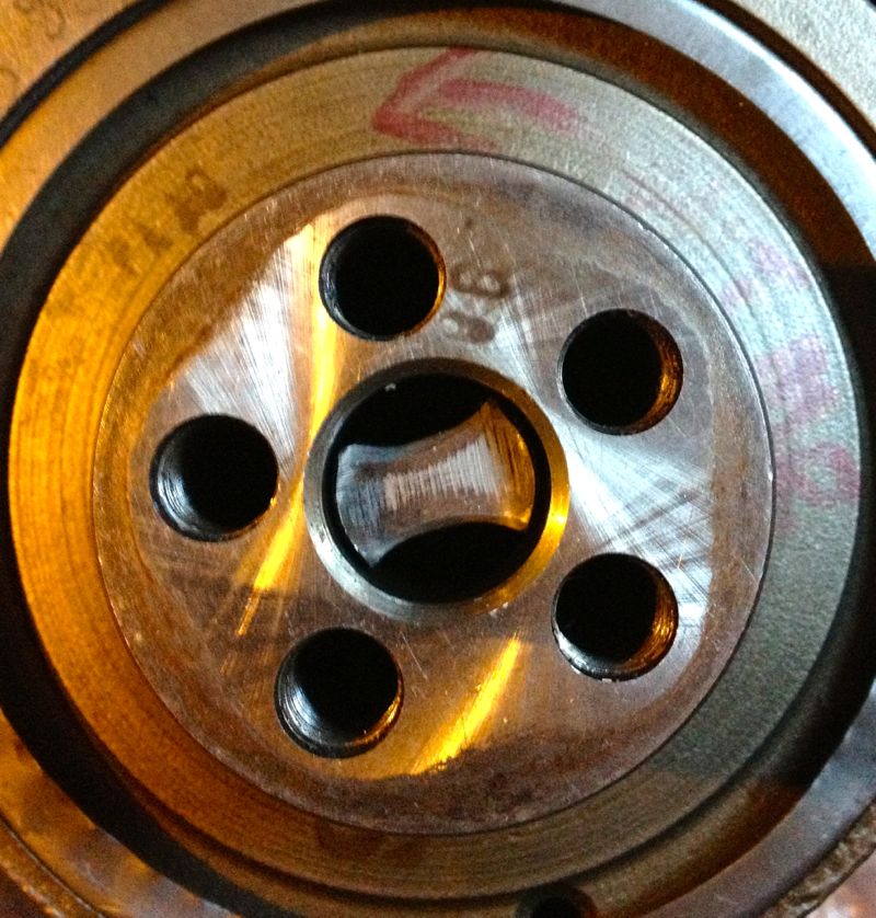
After making my crankshaft tool, I decided to test it out on Martin’s crankshaft, and pleasingly it went down the middle until it hit the rear crankshaft web. A quick close up snap will show the tool and crankshaft hole are not concentric.
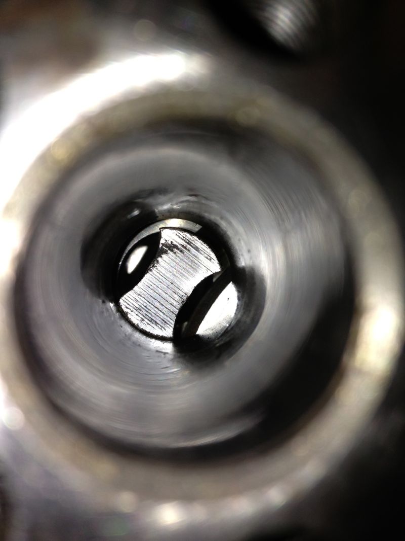
However, after looking at the crankshaft, a good swipe with a brand new #4 Thor from a decent height might suffice to put things right. It had to be bigger than my old crank bashing hammer, as these crankshafts have quite large pins, compared to the motorcycle crankshafts I have messed with in the past..Thor in right hand, crank in left, a couple of big swings and a few big hits later, and this is the result.
A quick check on the Alpha crankshaft truing rig, and it gets the all clear.
Now the question is do I leave it be, do i pin it or do I weld it with a pencil torch and TID set? I’ll let Martin make the decision.
UPDATE
He has and he’d like it pinning, so the saga continues...
Several months ago, Martin McClarence had given me an ex Woody crankshaft to true up that had turned somehow.
When he installed this low mileage crankshaft (10 miles) into his engine, it decided to let go a little and break the piston ring seal and damage the timing gear cover. I knew it was bent because Martin couldn’t fit the rear bearing plate in the crankcase, when the crankshaft was installed in the front bearing, and this was confirmed by the wobble I saw on the Alpha crank truing rig. It is very awkward to true one of these cranks on a traditional crankshaft rig, which is why making the special tool is so beneficial.
After making my crankshaft tool, I decided to test it out on Martin’s crankshaft, and pleasingly it went down the middle until it hit the rear crankshaft web. A quick close up snap will show the tool and crankshaft hole are not concentric.
However, after looking at the crankshaft, a good swipe with a brand new #4 Thor from a decent height might suffice to put things right. It had to be bigger than my old crank bashing hammer, as these crankshafts have quite large pins, compared to the motorcycle crankshafts I have messed with in the past..Thor in right hand, crank in left, a couple of big swings and a few big hits later, and this is the result.
A quick check on the Alpha crankshaft truing rig, and it gets the all clear.
Now the question is do I leave it be, do i pin it or do I weld it with a pencil torch and TID set? I’ll let Martin make the decision.
UPDATE
He has and he’d like it pinning, so the saga continues...
Comments
Panhard bare cylinder isn't tapered (updated)
Friday 02 November 2012 Filed in: Blog Comments
I have long said that boring a tapered liner is extremely difficult, and I often wondered how Panhard did it, but today I found out for sure.
I have measured the internal diameters of a bare aluminium cylinder casting, and it is truly parallel internally. I have also measured a new old stock liner and this was parallel internally and externally, so it was suggested by me, that Panhard machined a tapered liner was the stuff of legends or folklore.
I actually surprised myself by accidentally stumbling upon a method of boring a tapered liner the other day, and although I might still do this using the boring bar directly, I didn’t think this is what Panhard did, as it’s not really a production method. So how else could this be achieved?
It was possible that Panhard used a tapered honing process, but again it’s way too slow and therefore probably not what Panhard did either.
I knew the cylinder finning and casting were tapered, and I wondered whether this fact was lost in translation when the cylinder was being described in the press releases, but then I had my eureka moment and I discovered an even easier way. I was drawing up a new cylinder in CAD looking at the original casting, and taking measurements, when it hit me.
The answer lies in the liner or sleeve is an interference fit in the cylinder casting, and depending on the interference, the strength of the cylinder casting (thickness of the walls) this determines how much the liner distorts, this distortion is what tapers the cylinder bore.
When the bare cylinder is warmed up the interference fit is lost, and the cold liner or sleeve is “dropped” in place, but when it cools the cylinder starts to squeeze the liner. However the cylinder walls have different thicknesses tapering from the bottom of the liner to the top, as in the picture below.
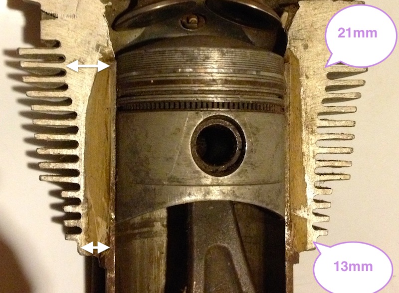
What this means is for a given interference fit along its length, the liner will be squeezed more at the top than the bottom, because the cylinder is much stiffer in compression at the top, and less stiff as the liner moves away from the top. The reality is on a cold bore today when it was 4ºC, the diameters measured across the liner from top to bottom are as shown.
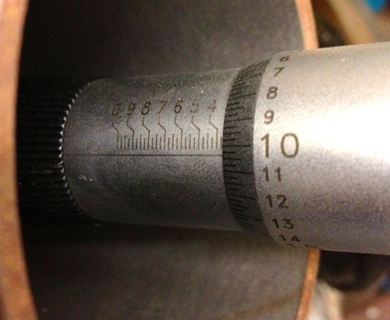
3.3604” at the very top (closest to the combustion chamber in the above photo)
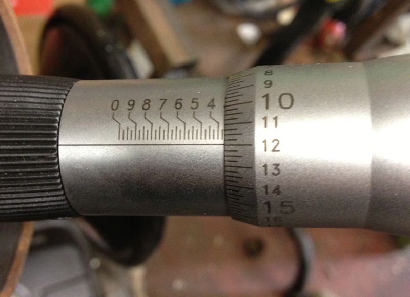
3.3620” in the middle of the liner, measured roughly in the middle of the cylinder casting.

3.3626” in the liner, measured at the base of the cylinder casting.
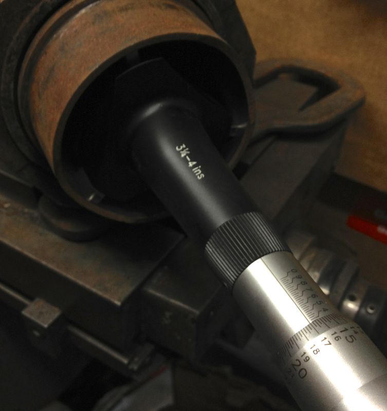
Lastly, at the base of the liner skirt, which is the bit that isn’t contained by the cylinder casting, that is where the spigot goes into the crankcase, the actual machined bore diameter of 3.3670” is seen again on the micrometer.
There is a 0.007” variation on a cold cylinder from top to bottom, and no wonder people often said some engines were quiet and slow running, until they warmed up slightly!
The mystery as to how the cylinder bore becomes tapered is finally solved for me at least, and possibly a few others too.
It also means you can parallel bore the cylinder casting or sleeve, and you will not destroy the factory taper, but you must always take the liner or sleeve out of the cylinder casting otherwise you will.
If you make a larger bore engine using the standard cylinder casting & original interference fit, you will reduce the taper effect at the top, because you have reduced the wall thickness and compressive stiffness pro rata.
I am almost ready to machine the cylinders to suit the new pistons, but I need to explore a couple of other things first, namely how perpendicular is the bore, and how does the cylinder bore change with temperature versus the piston crown & ring body, which will establish the actual bore size required for the liner or sleeve.
UPDATE Saturday 3 November 2012
It seems that at about a cylinder temperature of 120ºC the bore is truly parallel, and approximately 0.007” larger at the combustion chamber end of the liner, than when it is cold.
I have measured the internal diameters of a bare aluminium cylinder casting, and it is truly parallel internally. I have also measured a new old stock liner and this was parallel internally and externally, so it was suggested by me, that Panhard machined a tapered liner was the stuff of legends or folklore.
I actually surprised myself by accidentally stumbling upon a method of boring a tapered liner the other day, and although I might still do this using the boring bar directly, I didn’t think this is what Panhard did, as it’s not really a production method. So how else could this be achieved?
It was possible that Panhard used a tapered honing process, but again it’s way too slow and therefore probably not what Panhard did either.
I knew the cylinder finning and casting were tapered, and I wondered whether this fact was lost in translation when the cylinder was being described in the press releases, but then I had my eureka moment and I discovered an even easier way. I was drawing up a new cylinder in CAD looking at the original casting, and taking measurements, when it hit me.
The answer lies in the liner or sleeve is an interference fit in the cylinder casting, and depending on the interference, the strength of the cylinder casting (thickness of the walls) this determines how much the liner distorts, this distortion is what tapers the cylinder bore.
When the bare cylinder is warmed up the interference fit is lost, and the cold liner or sleeve is “dropped” in place, but when it cools the cylinder starts to squeeze the liner. However the cylinder walls have different thicknesses tapering from the bottom of the liner to the top, as in the picture below.
What this means is for a given interference fit along its length, the liner will be squeezed more at the top than the bottom, because the cylinder is much stiffer in compression at the top, and less stiff as the liner moves away from the top. The reality is on a cold bore today when it was 4ºC, the diameters measured across the liner from top to bottom are as shown.
3.3604” at the very top (closest to the combustion chamber in the above photo)
3.3620” in the middle of the liner, measured roughly in the middle of the cylinder casting.
3.3626” in the liner, measured at the base of the cylinder casting.
Lastly, at the base of the liner skirt, which is the bit that isn’t contained by the cylinder casting, that is where the spigot goes into the crankcase, the actual machined bore diameter of 3.3670” is seen again on the micrometer.
There is a 0.007” variation on a cold cylinder from top to bottom, and no wonder people often said some engines were quiet and slow running, until they warmed up slightly!
The mystery as to how the cylinder bore becomes tapered is finally solved for me at least, and possibly a few others too.
It also means you can parallel bore the cylinder casting or sleeve, and you will not destroy the factory taper, but you must always take the liner or sleeve out of the cylinder casting otherwise you will.
If you make a larger bore engine using the standard cylinder casting & original interference fit, you will reduce the taper effect at the top, because you have reduced the wall thickness and compressive stiffness pro rata.
I am almost ready to machine the cylinders to suit the new pistons, but I need to explore a couple of other things first, namely how perpendicular is the bore, and how does the cylinder bore change with temperature versus the piston crown & ring body, which will establish the actual bore size required for the liner or sleeve.
UPDATE Saturday 3 November 2012
It seems that at about a cylinder temperature of 120ºC the bore is truly parallel, and approximately 0.007” larger at the combustion chamber end of the liner, than when it is cold.
