2011
Panhard trigger wheel testing
Sunday 02 October 2011
Another few hours spent on this, testing various iterations of the firmwares with my cased MicroSquirts, and revisiting yesterdays efforts, as I made a number of teeth input error part way through my previous attempts. This only affects the early B&G firmware and MSExtra as they need the correct value inputting, whereas the later B&G 3.760 has an auto detect function called Auto Trigger.
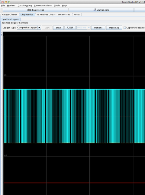
A quick screenshot of TunerStudio doing its stuff using the logging tools. The cyan columns are the 11 teeth, the gap the 12th missing tooth, and the red line on the bottom is the Sync errors, and because this line is straight there are none. Using MSExtra 3.1.0, I can get reliable sync from 45 rpm up to 11800 rpm using the Renault sensor and a 2mm air gap. I think if the trigger wheel is made thicker, it will allow me to increase the air gap to nearer 3mm, and I might make the teeth slightly less wide too.
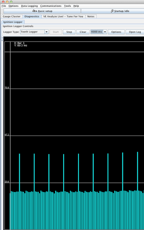
The screenshot below shows the tooth pattern, the 11vertical lines roughly the same size are the physical bumps or teeth, and the tallest column is the missing tooth area. This is what the ECU is seeing, but as this is using the motorised engine rig, so the variances between the 11 teeth are not very pronounced. However when this is used on a real engine the compression effects and the resulting slowing down of the trigger wheel attached to the crankshaft, shows itself in bigger variances in height.
A quick screenshot of TunerStudio doing its stuff using the logging tools. The cyan columns are the 11 teeth, the gap the 12th missing tooth, and the red line on the bottom is the Sync errors, and because this line is straight there are none. Using MSExtra 3.1.0, I can get reliable sync from 45 rpm up to 11800 rpm using the Renault sensor and a 2mm air gap. I think if the trigger wheel is made thicker, it will allow me to increase the air gap to nearer 3mm, and I might make the teeth slightly less wide too.
The screenshot below shows the tooth pattern, the 11vertical lines roughly the same size are the physical bumps or teeth, and the tallest column is the missing tooth area. This is what the ECU is seeing, but as this is using the motorised engine rig, so the variances between the 11 teeth are not very pronounced. However when this is used on a real engine the compression effects and the resulting slowing down of the trigger wheel attached to the crankshaft, shows itself in bigger variances in height.
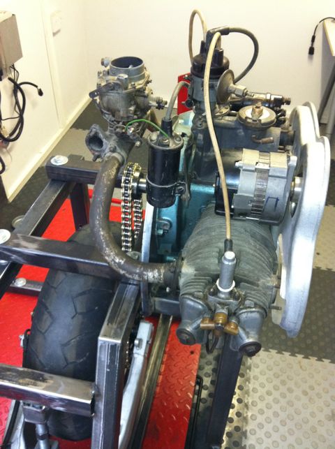
Panhard dynamo pulley on EFI rig
Saturday 01 October 2011
I managed to get a few timing wheels laser cut the other day, and the idea was to combine these with a Renault crankshaft sensor, so that I can create a timing trigger for the electronic ignition. I had done this with an earlier project, but now wanted to refine the set up further to allow for the fuel injection mods that will follow from this.
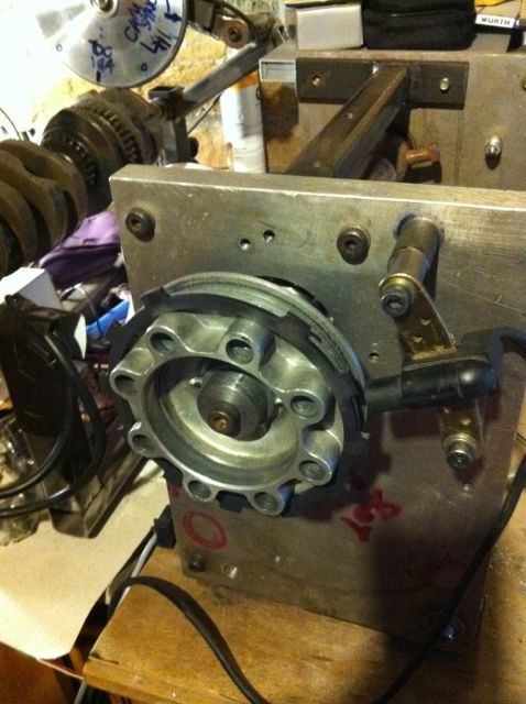
Here’s a pic of the first design effort, and there’s me thinking that a 3mm thick wheel would be sufficient for a 2mm sensor tip. At first it didn’t seem like it would be, and the disturbing thing is there is a slight eccentricity with these OEM pulleys, so a wider wheel might be useful to combat this. The reason why it wasn’t working as well as it should have done, was because I was putting the wrong values into the Number of Teeth box. I was inputting 8-1, when it was plainly a 12-1 wheel!

I was also swapping various v2 MicroSquirts & a v3 beta running different EFI firmwares including MSExtra 3.1 and, B&G 2.890, 3.430 & 3.760.
This 12-1 wheel design worked OK up to 3000 rpm, but then dropped out of sync, whereas the 6mm thick 36-1 wheel using the same sensor worked faultlessly from 50-11780 rpm, so despite the initial input error, the trigger wheel is too thin.
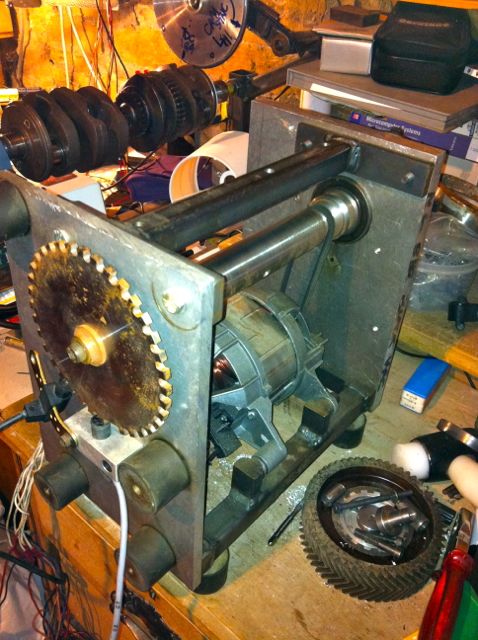
This is the old washing machine motor from a 1986 Hotpoint ℅ Siemens Gmbh dropped into my DIY engine rig. I have had to fit a poly-vee belt reduction gear, as this thing will rev to 22,000 RPM in 1:1 mode!
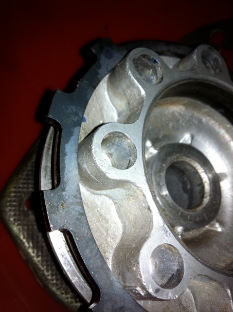
Note. Bottom right, inside the chevron cut fibre camshaft timing gear are the revised oil light pistons I made in the 1990’s to combat the lubrication faults with the Panhard engine. The picture below shows an incomplete one, with the revised lubrication to the timing gear (there is a relief valve, ball, spring with a set screw yet to be inserted in the middle).
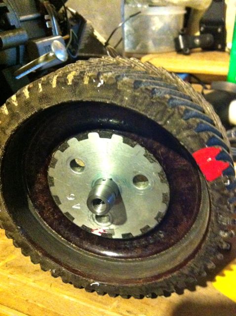
Also can you spot the crankshaft & cam rig in the background, above this picture, which is still being used to develop the MicroSquirt based EFI systems for the GTS1000 & Thunderace motorcycle engines :)
Here’s a pic of the first design effort, and there’s me thinking that a 3mm thick wheel would be sufficient for a 2mm sensor tip. At first it didn’t seem like it would be, and the disturbing thing is there is a slight eccentricity with these OEM pulleys, so a wider wheel might be useful to combat this. The reason why it wasn’t working as well as it should have done, was because I was putting the wrong values into the Number of Teeth box. I was inputting 8-1, when it was plainly a 12-1 wheel!
I was also swapping various v2 MicroSquirts & a v3 beta running different EFI firmwares including MSExtra 3.1 and, B&G 2.890, 3.430 & 3.760.
This 12-1 wheel design worked OK up to 3000 rpm, but then dropped out of sync, whereas the 6mm thick 36-1 wheel using the same sensor worked faultlessly from 50-11780 rpm, so despite the initial input error, the trigger wheel is too thin.
This is the old washing machine motor from a 1986 Hotpoint ℅ Siemens Gmbh dropped into my DIY engine rig. I have had to fit a poly-vee belt reduction gear, as this thing will rev to 22,000 RPM in 1:1 mode!
Note. Bottom right, inside the chevron cut fibre camshaft timing gear are the revised oil light pistons I made in the 1990’s to combat the lubrication faults with the Panhard engine. The picture below shows an incomplete one, with the revised lubrication to the timing gear (there is a relief valve, ball, spring with a set screw yet to be inserted in the middle).
Also can you spot the crankshaft & cam rig in the background, above this picture, which is still being used to develop the MicroSquirt based EFI systems for the GTS1000 & Thunderace motorcycle engines :)
Panhard oil light piston wear update
Friday 23 September 2011
The original oil light was a machined cast lump…
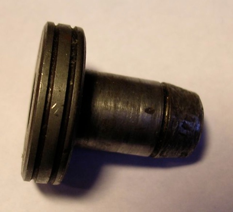
so I created this replacement in mild steel. This is the basic part, because I hand finish this further.
This is used with other mods to refine the Panhard oil lubrication circuits. The nose was rounded in the picture below to prevent wearing out the wooden plug that pushes the oil light contact, once the engine gets up to pressure.
I happened to be stripping an engine to use in my EFI project, and I came across this, which was an earlier prototype 1990’s part that I fitted to an engine in 2002, and because I was relying on splash and bleeding from the oil ways nearby, it didn’t need the cross drilling.
Interestingly, there is no wear to the wooden block below, and additionally there is no cross drilling to increase the oil supply to the camshaft timing gears this version, whereas there was in later engines I built. One of the reasons for examining this, was the owner said the camshaft gear was noisier than he remembered previously, and although the aluminium gear is when compared against the OEM fibre wheel, I’d thought I’d investigate further.
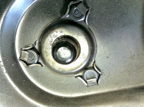
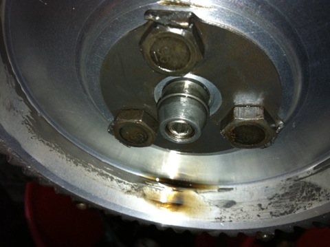
Picture above shows the oil light insulator button from inside the camshaft timing gear case, which acts an insulator and breaks the brass contact for the dash mounted low oil pressure warning light earth loop, but only as the oil pressure in the hollow camshaft gallery builds up.
It’s more remarkable, because this particular engine had very little additional lubrication, other than a little splash bleed from nearby oil galleries, and was the first one where I altered the crankcase lubrication circuits.
This is great news, as I now don’t need to do the brass nosing mod, as shown below, which I did in 2004.
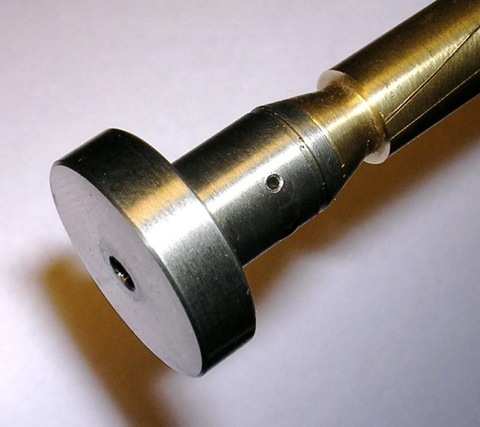
This was done to an earlier engine rebuild for a two bladed fan Dyna engine, because I was concerned about the potential friction that the hollow threaded tip of the piston might create.
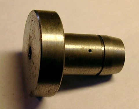
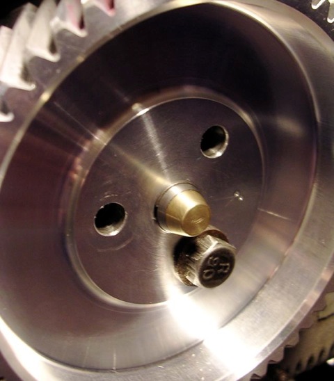
This is the later revision to the oil light circuit, and although it’s incomplete, you can see there is a cross drilling that is exposed once the oil pressure builds up in the camshaft gallery. The relief valve can be set, so that the first priority is the crankshaft big end rollers, and the hole size can be varied if more lubrication is needed to these timing gears. However, as this oil feed is off the central oil gallery within the camshaft, there is no pressure fluctuations as the camshaft rotates to either big end bearing, so eliminating all the developmental faults that were introduced as the years went by.
so I created this replacement in mild steel. This is the basic part, because I hand finish this further.
This is used with other mods to refine the Panhard oil lubrication circuits. The nose was rounded in the picture below to prevent wearing out the wooden plug that pushes the oil light contact, once the engine gets up to pressure.
I happened to be stripping an engine to use in my EFI project, and I came across this, which was an earlier prototype 1990’s part that I fitted to an engine in 2002, and because I was relying on splash and bleeding from the oil ways nearby, it didn’t need the cross drilling.
Interestingly, there is no wear to the wooden block below, and additionally there is no cross drilling to increase the oil supply to the camshaft timing gears this version, whereas there was in later engines I built. One of the reasons for examining this, was the owner said the camshaft gear was noisier than he remembered previously, and although the aluminium gear is when compared against the OEM fibre wheel, I’d thought I’d investigate further.
Picture above shows the oil light insulator button from inside the camshaft timing gear case, which acts an insulator and breaks the brass contact for the dash mounted low oil pressure warning light earth loop, but only as the oil pressure in the hollow camshaft gallery builds up.
It’s more remarkable, because this particular engine had very little additional lubrication, other than a little splash bleed from nearby oil galleries, and was the first one where I altered the crankcase lubrication circuits.
This is great news, as I now don’t need to do the brass nosing mod, as shown below, which I did in 2004.
This was done to an earlier engine rebuild for a two bladed fan Dyna engine, because I was concerned about the potential friction that the hollow threaded tip of the piston might create.
This is the later revision to the oil light circuit, and although it’s incomplete, you can see there is a cross drilling that is exposed once the oil pressure builds up in the camshaft gallery. The relief valve can be set, so that the first priority is the crankshaft big end rollers, and the hole size can be varied if more lubrication is needed to these timing gears. However, as this oil feed is off the central oil gallery within the camshaft, there is no pressure fluctuations as the camshaft rotates to either big end bearing, so eliminating all the developmental faults that were introduced as the years went by.
Panhard cylinder
Saturday 09 July 2011
Panhard cylinder heads and barrels are a one piece assembly, very similar to early aero engines, which incidentally removes any chance of head gasket failures, but this makes machining them awkward. Technology has moved on and it’s not the norm to manufacture engines like this, and in fact Porsche engines pro rata manage to make more horsepower using similar materials incorporating head gaskets, without suffering from reliability issues.
For my engine work, it was always going to be necessary to revisit the cylinder construction, and again many years ago I separated a head from a cylinder, as a design exercise to investigate the feasibility of modifying these components, and making new parts. I remember doing this in the lathe, and the cooling fins from the barrel only just cleared the toolholder, but when they were separated and you could see the individual pieces, it was obvious to me this was the only way to go, if you wanted to bring the engines into the 21st century. Panhard tapered the liners, and used split skirt pistons with hemispherical combustion chambers, which was OK in the 1940s, but current combustion chamber thinking is moving towards minimal surface areas and squish, with reduced ignition advance.
Cylinder and coating technology has moved on as well, so whereas VW would use a Biral cylinder in the 80’s, quite similar to a Panhard with a steel liner and aluminium finning, others in motorcycling and karting were using all aluminium construction for their cylinder construction with Nikasil plating for the piston surfaces. Early plating processes were responsible for a few engine failures over time, with plating separation at the head gasket/ cylinder interfaces causing all sorts of issues, especially in higher performance engines with detonation.
Fortunately, thanks in part to the space programme and the accelerated development of ceramics, there are better alternatives available now with amazing potential. Aluminium is now used in tool steel injection moulding machines with coatings applied, that offer better thermal and longer life than their steel equivalents, plus the coating deposition processes have become much better environmentally and from a tribological viewpoint are now second to none and so used extensively in high performance engines.
What does this mean for Panhards, well you could remove the heads, make new cylinders with increased finning to dissipate the heat, just like others did in WWII, as air cooled engine performance was boosted in fighter aircraft. At the same time, eliminate the steel liner using modern coating technology, and safely increase the performance margins, as a cooler cylinder would keep heat away from the cylinder heads, and no liner would negate differing thermal expansion rates. The coatings technology would secure long life, corrosion protection and a restoration route if required.
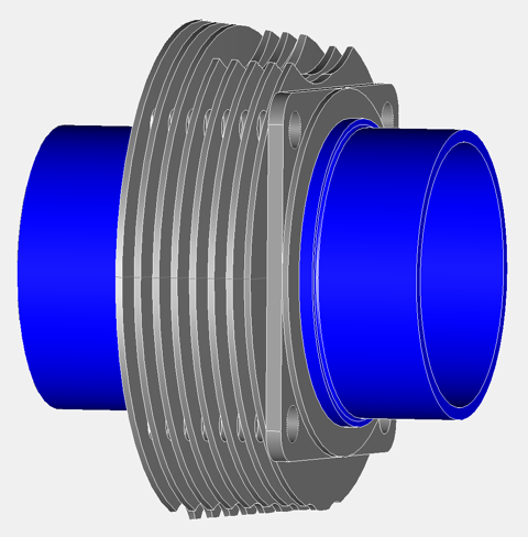
A standard cylinder has eight fins under the head like the drawing below.
Mine will have...well you have to wait! Anyway there are other priorities first, because there’s no use making cylinders that increase performance, as the crankshaft is undoubtedly the weakest link. Peter Breed in Holland offers a first class crankshaft service, with bespoke connecting rods and new pistons to rebored OEM cylinders. It is a good system, and was the most cost effective route at the time, and probably still is. How do I know, well I worked with Peter on this solution, but it relies on a having a salvageable crankshaft at the start and that’s why I am developing a new remanufacturing process, because I want to salvage these tired, pitted and corroded crankshafts.
For my engine work, it was always going to be necessary to revisit the cylinder construction, and again many years ago I separated a head from a cylinder, as a design exercise to investigate the feasibility of modifying these components, and making new parts. I remember doing this in the lathe, and the cooling fins from the barrel only just cleared the toolholder, but when they were separated and you could see the individual pieces, it was obvious to me this was the only way to go, if you wanted to bring the engines into the 21st century. Panhard tapered the liners, and used split skirt pistons with hemispherical combustion chambers, which was OK in the 1940s, but current combustion chamber thinking is moving towards minimal surface areas and squish, with reduced ignition advance.
Cylinder and coating technology has moved on as well, so whereas VW would use a Biral cylinder in the 80’s, quite similar to a Panhard with a steel liner and aluminium finning, others in motorcycling and karting were using all aluminium construction for their cylinder construction with Nikasil plating for the piston surfaces. Early plating processes were responsible for a few engine failures over time, with plating separation at the head gasket/ cylinder interfaces causing all sorts of issues, especially in higher performance engines with detonation.
Fortunately, thanks in part to the space programme and the accelerated development of ceramics, there are better alternatives available now with amazing potential. Aluminium is now used in tool steel injection moulding machines with coatings applied, that offer better thermal and longer life than their steel equivalents, plus the coating deposition processes have become much better environmentally and from a tribological viewpoint are now second to none and so used extensively in high performance engines.
What does this mean for Panhards, well you could remove the heads, make new cylinders with increased finning to dissipate the heat, just like others did in WWII, as air cooled engine performance was boosted in fighter aircraft. At the same time, eliminate the steel liner using modern coating technology, and safely increase the performance margins, as a cooler cylinder would keep heat away from the cylinder heads, and no liner would negate differing thermal expansion rates. The coatings technology would secure long life, corrosion protection and a restoration route if required.
A standard cylinder has eight fins under the head like the drawing below.
Mine will have...well you have to wait! Anyway there are other priorities first, because there’s no use making cylinders that increase performance, as the crankshaft is undoubtedly the weakest link. Peter Breed in Holland offers a first class crankshaft service, with bespoke connecting rods and new pistons to rebored OEM cylinders. It is a good system, and was the most cost effective route at the time, and probably still is. How do I know, well I worked with Peter on this solution, but it relies on a having a salvageable crankshaft at the start and that’s why I am developing a new remanufacturing process, because I want to salvage these tired, pitted and corroded crankshafts.
Panhard dynamo pulley
Sunday 03 July 2011
I recently bought a newer CAD package, so rather than use Ashlar Vellum from the late 80’s on a G4 Cube, I can now use my Intel iMac & MacBook Pro, which are significantly faster. The software also has a number of export options, and I recently did a test .dxf file export to a laser cutting company, and everything translated between the differing computer platforms & softwares flawlessly. The parts were used in the engine stand.
To get used to the software some more, I started to redraw some Panhard components, that I had drawn up years ago, but were in the older format. This is the start of the new dynamo pulley, which is really going to become an alternator pulley. It should be obvious which is which if you’ve seen the components before, but original part is the bottom image, with the my updated version on top.
Final timing gear design, 60-2 drawn, or pulley drive belt section not fixed yet, as aftermarket low cost alternator or the VR sensor location isn’t finalised.
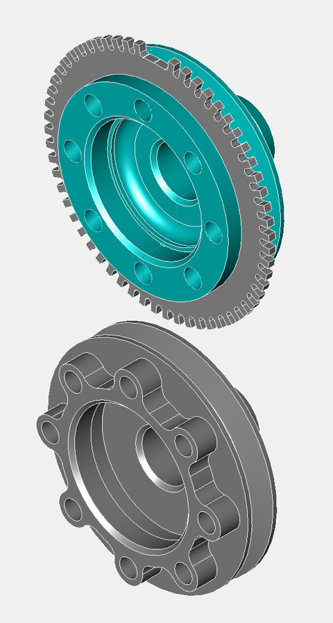
Panhard engine stand
Thursday 30 June 2011
A long time ago I needed to test my Panhard engines, and as I didn’t have a car on the road, an engine dyno would have been the next best thing. However finding one is another story, so I did the next best thing, found a roller dyno and thought about making an engine frame that’ll drive it. I was lucky there was an inertial dyno about two miles from me, but I never did get chance to make the “motorised wheelbarrow” that would bolt to it, as I put the engine in a Panhard PL17 and it worked so well, that it was obvious at the time there were improvements, so the need to construct something fell by the wayside.
Fast forward several years later, fuel injection projects on my motorcycle engines, FZR1000, GTS1000 & YZF1000, mean an engine dyno is an essential requirement to do this work properly. As I won’t be putting a Panhard on the road short term, and I’d like to benchmark these engines too, so it makes sense to revisit the engine dyno project again, but allow for & consider both these options at the same time.
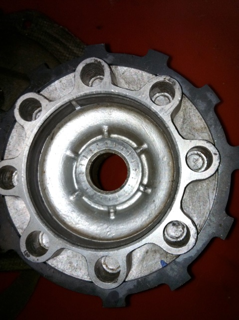
The bike engine is straightforward as it is chain driven, but the Panhard isn’t, so I’d have to convert the flywheel to accept chain drive, as you can see in the picture below. This is the unfinished raw metal version complete with a dummy engine, which is a partial crankcase and a split cylinder & head from another project. I needed to make sure the engine support plate cleared the inlet manifold stubs, which it does now.
The engine frame is not fastened to the wheel subframe when the picture was taken, and neither is the sprocket is, as I am trying to keep the chain tension and length the same for any combo of engine rig I use, and I need to keep disassembling the stand and fitting other parts. If I can keep the same chain, it will simplify the swap over process, and so make the installation of other engines easier. Additionally, I am going to convert this into a freestanding engine stand, so I need to make a simple rear support frame, which will probably be a folding structure, probably like an ironing board stand, that tucks out of the way as I slide the engine rig onto the wheel rig. This means I can do basic run tests without the dyne, and free up dyne room for other projects.
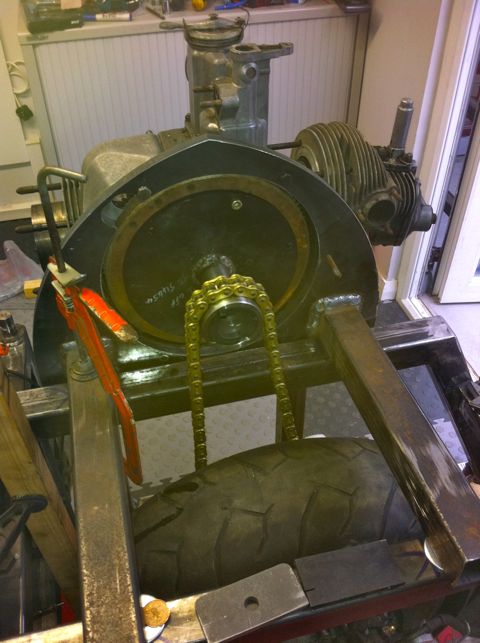
In the latest pic, everything seems to check out, as I now have a virtually complete engine fitted. It looks like I don’t need any extra brackets welding to the frame other than a battery support & the associated control panel shelf, so I will be sending it off to the powder coaters soon. Alternator conversion was a previous modification that had been dormant for a few years too, and it was a nice tidy fit at the time, however it’s powered by Lucas, so that probably won’t appeal to our French cousins! However these alternators are great value for money compared to the smaller Denso units, and readily available.
Fast forward several years later, fuel injection projects on my motorcycle engines, FZR1000, GTS1000 & YZF1000, mean an engine dyno is an essential requirement to do this work properly. As I won’t be putting a Panhard on the road short term, and I’d like to benchmark these engines too, so it makes sense to revisit the engine dyno project again, but allow for & consider both these options at the same time.
The bike engine is straightforward as it is chain driven, but the Panhard isn’t, so I’d have to convert the flywheel to accept chain drive, as you can see in the picture below. This is the unfinished raw metal version complete with a dummy engine, which is a partial crankcase and a split cylinder & head from another project. I needed to make sure the engine support plate cleared the inlet manifold stubs, which it does now.
The engine frame is not fastened to the wheel subframe when the picture was taken, and neither is the sprocket is, as I am trying to keep the chain tension and length the same for any combo of engine rig I use, and I need to keep disassembling the stand and fitting other parts. If I can keep the same chain, it will simplify the swap over process, and so make the installation of other engines easier. Additionally, I am going to convert this into a freestanding engine stand, so I need to make a simple rear support frame, which will probably be a folding structure, probably like an ironing board stand, that tucks out of the way as I slide the engine rig onto the wheel rig. This means I can do basic run tests without the dyne, and free up dyne room for other projects.
In the latest pic, everything seems to check out, as I now have a virtually complete engine fitted. It looks like I don’t need any extra brackets welding to the frame other than a battery support & the associated control panel shelf, so I will be sending it off to the powder coaters soon. Alternator conversion was a previous modification that had been dormant for a few years too, and it was a nice tidy fit at the time, however it’s powered by Lucas, so that probably won’t appeal to our French cousins! However these alternators are great value for money compared to the smaller Denso units, and readily available.
Panhard rebirth
Thursday 23 June 2011
Panhard work is being restarted and now I’m going to get serious. It’s been a long time coming, but thanks to my other interests, I have some new tricks up my sleeve…traditionalists beware. Read More...