2012
Panhard crankcase oil circulation faults (revisited)
Saturday 03 March 2012
A quick history lesson on Panhard engine failures. The front main bearing and front cylinder crankshaft big end started to develop failures, as they increased the horsepower. It was attributed to insufficient oil supply, and so the front end lubrication was revised, and the camshaft timing gears were used as a splash lubrication system and the oil drilling that provided that role under the front main bearing was removed. This modification was introduced from around the early 1960’s, and ran to the end of production in 1967.
Unfortunately for Panhard they were barking up the wrong tree, despite the engine coming from a well thought out design originally, other people tinkered with the design knee jerk fashion as the problems developed, and nobody took an overview and look at the root causes. The financial woes and Citröen management probably didn’t help, but as Panhard died in 1967, we will never really know.
Flash forward to the next century, and if you are running one of these engines, it will almost be suffering from the result of this modification. As the engine ages the oil pump becomes more marginal, so the front bearings don’t really fatigue like they used to, but the rears suffer now. So the problem has transferred itself, and the question that should be asked is why?
Of course if you look at the development of these engines you will read about the engines modified for endurance racing, which had higher capacity pumps, and an increased oil capacity with the fitment of an additional sump, that also acted as a baffled cavity for the oil pick up pipe. This subset of development has been an evolutionary branch of Panhard engine that needs revising, because if you really look at the problem, these solutions are papering over the cracks of a design fault. If you go back in time, and look at other engine design of the Panhard flat twin, there are numerous good points. The oil supply is essentially a low pressure system, and the design of the original plain bearing surfaces reflect this.
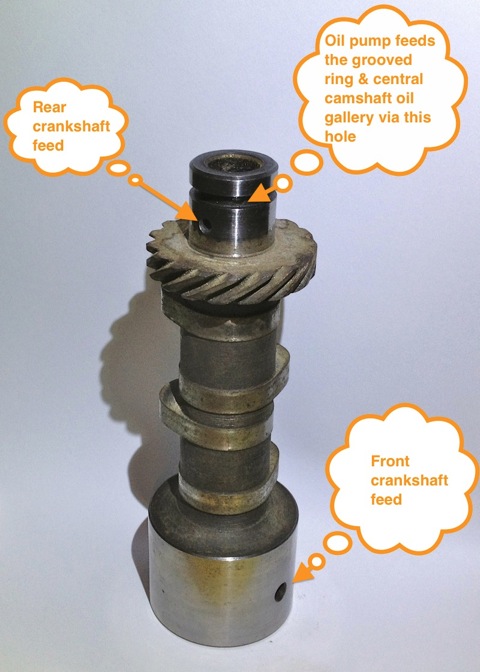
For example in the front bearing of the camshaft, which has a very large diameter at the front where the timing gear is driven by the crankshaft, and a more normal sized bearing diameter at the rear. Also, if you look at the oil drillings that feed these plain bearings, they are proportionately scaled to suit. The camshaft is the common denominator in all of this because it is one of three main oil feeds from the oil pump, and the supply conduit for the front and rear main bearings and the crankshaft lubrication, but wasn’t there a problem here?
So how can a central oil gallery that feeds both the front and rear crankshafts be at fault? Actually, the central gallery is not the problem, because the flow into this is separate from the outputs, and if you look at these, the problem is almost explained. The original design knew he needed to equalise the distribution of the oil, so the oil outputs for the front and rear crankshaft feeds are phased to do just this, and as the cross drillings are on a rotating surface the timing window on the camshafts are scaled accordingly. However, although the rear crankshaft oil drilling is sized to match the rear camshaft drilling, the front is mismatched, because the oil drilling in the crankcase is too small.
On examination the oil drilling needs to be around 6mm diameter, when it is only 4mm, which is a 50% reduction in oil supply compared to the rear, and this alone would explain the front end failure susceptibility, but it doesn’t end there. The original designer tried to phase the oil supply to the front and rear ends equally, but somebody decided the camshaft timing gear at the front should have some more lubrication, and put in an additional drilling. The reality was that the original plain bearing would have leaked into this cavity, and as there were no low level drainage holes, the oil wouldn’t go away, so it really didn’t need the additional drilling, but the biggest problem was where it was positioned. The oil pump doesn’t need to be big, as the engine only needed low flow rates and low pressure to work within it original design specifications, however any pressure drop say after a drilling would take a little time to recover, and this was accepted in the design layout, but as soon as the oil drilling to the front timing gear was placed ahead of the front end oil supply, the 50% reduction in flow rate all things being equal just got worse, as this drilling lost pressure after 60 degrees of a 90 degree recovery window, and only gave the camshaft 30 degrees to recover the oil pressure in the gallery. This means the front crankshaft oil feeds are compromised further, whereas the rears are unaffected, and it was all down to a simple production oversight.
What is the solution? Again, a quick history lesson will tell you all you need to know, and it is the route of many flat twin Panhard devotees, but don’t bother what you have to do is engine specific, but that’ll be another day. Suffice to say, I spotted this many years ago, and have been making parts and modding a few engines to overcome these oil related faults every time I get hold of one.
Unfortunately for Panhard they were barking up the wrong tree, despite the engine coming from a well thought out design originally, other people tinkered with the design knee jerk fashion as the problems developed, and nobody took an overview and look at the root causes. The financial woes and Citröen management probably didn’t help, but as Panhard died in 1967, we will never really know.
Flash forward to the next century, and if you are running one of these engines, it will almost be suffering from the result of this modification. As the engine ages the oil pump becomes more marginal, so the front bearings don’t really fatigue like they used to, but the rears suffer now. So the problem has transferred itself, and the question that should be asked is why?
Of course if you look at the development of these engines you will read about the engines modified for endurance racing, which had higher capacity pumps, and an increased oil capacity with the fitment of an additional sump, that also acted as a baffled cavity for the oil pick up pipe. This subset of development has been an evolutionary branch of Panhard engine that needs revising, because if you really look at the problem, these solutions are papering over the cracks of a design fault. If you go back in time, and look at other engine design of the Panhard flat twin, there are numerous good points. The oil supply is essentially a low pressure system, and the design of the original plain bearing surfaces reflect this.
For example in the front bearing of the camshaft, which has a very large diameter at the front where the timing gear is driven by the crankshaft, and a more normal sized bearing diameter at the rear. Also, if you look at the oil drillings that feed these plain bearings, they are proportionately scaled to suit. The camshaft is the common denominator in all of this because it is one of three main oil feeds from the oil pump, and the supply conduit for the front and rear main bearings and the crankshaft lubrication, but wasn’t there a problem here?
So how can a central oil gallery that feeds both the front and rear crankshafts be at fault? Actually, the central gallery is not the problem, because the flow into this is separate from the outputs, and if you look at these, the problem is almost explained. The original design knew he needed to equalise the distribution of the oil, so the oil outputs for the front and rear crankshaft feeds are phased to do just this, and as the cross drillings are on a rotating surface the timing window on the camshafts are scaled accordingly. However, although the rear crankshaft oil drilling is sized to match the rear camshaft drilling, the front is mismatched, because the oil drilling in the crankcase is too small.
On examination the oil drilling needs to be around 6mm diameter, when it is only 4mm, which is a 50% reduction in oil supply compared to the rear, and this alone would explain the front end failure susceptibility, but it doesn’t end there. The original designer tried to phase the oil supply to the front and rear ends equally, but somebody decided the camshaft timing gear at the front should have some more lubrication, and put in an additional drilling. The reality was that the original plain bearing would have leaked into this cavity, and as there were no low level drainage holes, the oil wouldn’t go away, so it really didn’t need the additional drilling, but the biggest problem was where it was positioned. The oil pump doesn’t need to be big, as the engine only needed low flow rates and low pressure to work within it original design specifications, however any pressure drop say after a drilling would take a little time to recover, and this was accepted in the design layout, but as soon as the oil drilling to the front timing gear was placed ahead of the front end oil supply, the 50% reduction in flow rate all things being equal just got worse, as this drilling lost pressure after 60 degrees of a 90 degree recovery window, and only gave the camshaft 30 degrees to recover the oil pressure in the gallery. This means the front crankshaft oil feeds are compromised further, whereas the rears are unaffected, and it was all down to a simple production oversight.
What is the solution? Again, a quick history lesson will tell you all you need to know, and it is the route of many flat twin Panhard devotees, but don’t bother what you have to do is engine specific, but that’ll be another day. Suffice to say, I spotted this many years ago, and have been making parts and modding a few engines to overcome these oil related faults every time I get hold of one.
Panhard front pulley with trigger wheel
Sunday 26 February 2012
I have made several distributor based electronic ignition prototypes over the years, and although cost effective, they all have a lack of precision, because they run through the existing drive mechanisms, which are a slotted drive on the end of a geared oil pump, which is powered by another gear on the gear driven camshaft.
Ultimately I need to fit a crankshaft timing trigger to this engine, as part of the ongoing ignition & fuelling developments, and the traditional locations for these are the flywheel or front pulley. If I want to gear this up for retrospective and easy fitment, the flywheel really is out of the question, because this is an engine out exercise in a Panhard, and that is a no brainer.
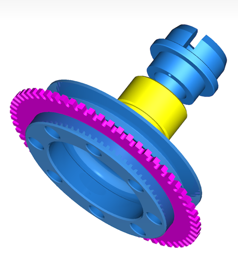
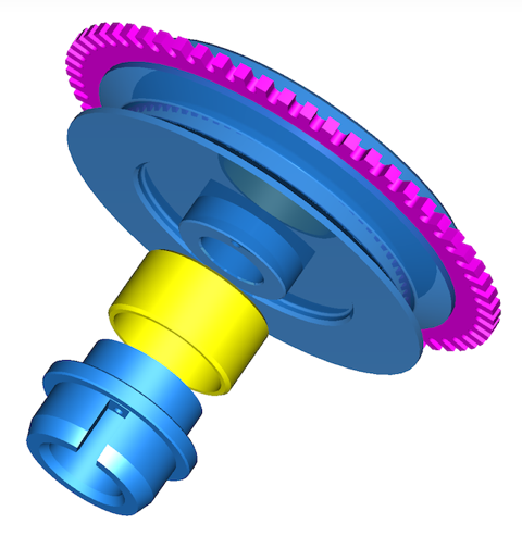
That now means the front pulley arrangement has the most potential, and that is what the majority of modern car manufacturers use anyway. Although it is possible to add a trigger wheel to the existing pulley, like I have done in my bench testing to date, there is a slight variance in sizes that negates this. It’s my philosophy to always make new parts wherever possible, so that old ones don’t get destroyed unnecessarily. At the same time there might be other design changes or benefits you can bring to this area, so for example I can incorporate a modern oil seal, assuming you tweak the timing gear casing, and also make the pulley rebuildable. If this is not to your liking, and you want to keep the OEM piston ring seal the design can be modified to accommodate this too, by replacing the yellow part for another.
Latest CAD thoughts are pictured below, and the pulley now has a renewable inner ring shown in yellow, which acts as a running surface for the double lipped oil seal. The aluminium parts in blue now have a location dowel for timing purposes. The trigger wheel shown in purple is also a standard 60-2 pattern, which gives improved triggering over the lesser toothed versions I was experimenting with.
Next up, look at the VR sensor support bracket, chase up the pistons, and hopefully acquire a boring machine.
Ultimately I need to fit a crankshaft timing trigger to this engine, as part of the ongoing ignition & fuelling developments, and the traditional locations for these are the flywheel or front pulley. If I want to gear this up for retrospective and easy fitment, the flywheel really is out of the question, because this is an engine out exercise in a Panhard, and that is a no brainer.
That now means the front pulley arrangement has the most potential, and that is what the majority of modern car manufacturers use anyway. Although it is possible to add a trigger wheel to the existing pulley, like I have done in my bench testing to date, there is a slight variance in sizes that negates this. It’s my philosophy to always make new parts wherever possible, so that old ones don’t get destroyed unnecessarily. At the same time there might be other design changes or benefits you can bring to this area, so for example I can incorporate a modern oil seal, assuming you tweak the timing gear casing, and also make the pulley rebuildable. If this is not to your liking, and you want to keep the OEM piston ring seal the design can be modified to accommodate this too, by replacing the yellow part for another.
Latest CAD thoughts are pictured below, and the pulley now has a renewable inner ring shown in yellow, which acts as a running surface for the double lipped oil seal. The aluminium parts in blue now have a location dowel for timing purposes. The trigger wheel shown in purple is also a standard 60-2 pattern, which gives improved triggering over the lesser toothed versions I was experimenting with.
Next up, look at the VR sensor support bracket, chase up the pistons, and hopefully acquire a boring machine.