GTS1000 Electrical
GTS1000 HID Headlight Conversion
Sat 18 Aug 2007
My bike was a Swiss model originally, which was fitted with a single H4, Hi/Lo bulb, so I changed it for a UK spec headlight which came with a split reflector design, comprising of a H4 Hi/Lo Beam (Main/Dip) section and a H3 Hi Beam (Main) section.
The only issue was the lighting was poor. At moderate speeds on a country lane, you’d drive on Lo or dip beam and have your finger on the flash button, as you accelerated out of the corners or braked into them, just to light up enough road...something had to be done. I needed to upgrade the lighting, and first choice is better bulbs. I did try a 100/80W unit, but although better, things got a little too warm. Then I read about HIDs, 3x the light output for 2/3rds the power, so a 55W bulb was replaced by a 35W unit. The way they work is they use a step up unit to create high (kV) voltage and use an arc process to create the light. As they don’t rely on heating a coil of wire, generating heat and a small amount of light they are more efficient.
I looked at acquiring some HIDs in the UK, but they were way top heavy, so I looked elsewhere, good ‘ol China c/o eBay, and noted I’d need a H4 & H3 set up, which I duly ordered and eagerly awaited their arrival, as I wanted to fit them before the 2007 Treffen.
When they arrived, I whipped off the sidepanels and front fairing, and investigated a place to put them. The only problem it was chucking it down with rain, so I built a makeshift tent, using a leftover climbing rope, and a tarpaulin.
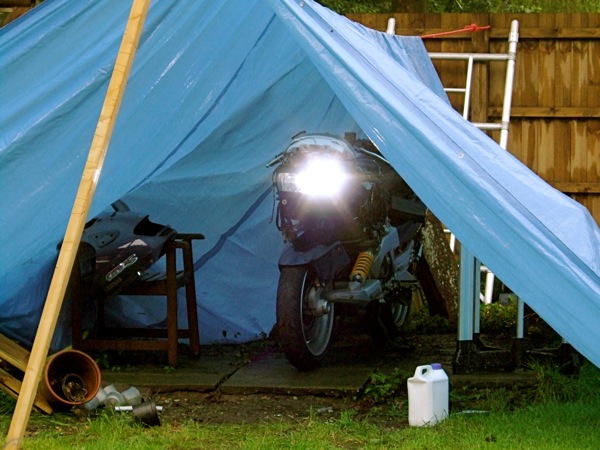
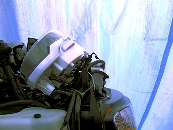
Above, GTS1000 in a makeshift tent, very wet outside, but HIDs working, and that’s just Lo or dip beam, plus I am not looking at it!
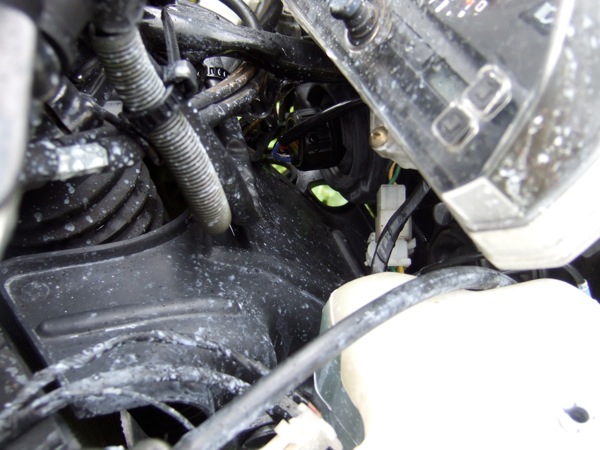
Looking at the space available, couldn’t really fit them around the steering column. The stains are from blowing anti-freeze, due to a faulty coolant reservoir cap rubber.
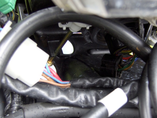
Neither was the space under the headlight any good, pictured above, but the area above the headlight showed the most promise, pictured below.
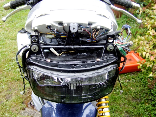
So that’s where the igniters went...
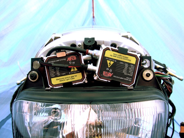
... and you could still get the front fairing cowl on...
Job well done, and a lot brighter.
The only issue was the lighting was poor. At moderate speeds on a country lane, you’d drive on Lo or dip beam and have your finger on the flash button, as you accelerated out of the corners or braked into them, just to light up enough road...something had to be done. I needed to upgrade the lighting, and first choice is better bulbs. I did try a 100/80W unit, but although better, things got a little too warm. Then I read about HIDs, 3x the light output for 2/3rds the power, so a 55W bulb was replaced by a 35W unit. The way they work is they use a step up unit to create high (kV) voltage and use an arc process to create the light. As they don’t rely on heating a coil of wire, generating heat and a small amount of light they are more efficient.
I looked at acquiring some HIDs in the UK, but they were way top heavy, so I looked elsewhere, good ‘ol China c/o eBay, and noted I’d need a H4 & H3 set up, which I duly ordered and eagerly awaited their arrival, as I wanted to fit them before the 2007 Treffen.
When they arrived, I whipped off the sidepanels and front fairing, and investigated a place to put them. The only problem it was chucking it down with rain, so I built a makeshift tent, using a leftover climbing rope, and a tarpaulin.
Above, GTS1000 in a makeshift tent, very wet outside, but HIDs working, and that’s just Lo or dip beam, plus I am not looking at it!
Looking at the space available, couldn’t really fit them around the steering column. The stains are from blowing anti-freeze, due to a faulty coolant reservoir cap rubber.
Neither was the space under the headlight any good, pictured above, but the area above the headlight showed the most promise, pictured below.
So that’s where the igniters went...
... and you could still get the front fairing cowl on...
Job well done, and a lot brighter.
Comments
Odometer, tripmeter conversion
Sat 09 Dec 2006
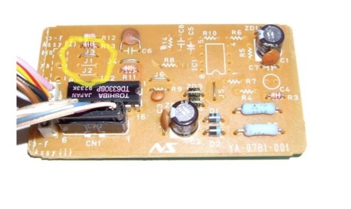
Whilst looking at the instrument panel and the speedo assembly last time, I noticed the board had some jumpers missing, which related to the external divisor pins for the IC that converts the front wheel pulses into a speedo signal. These were also used to feed the electric motors that power the odometer and tripmeter assembly. I wondered whether this was the kilometer or mile conversion area, or whether it was mechanical via the gearing.
I managed to get hold of a kilometer unit, and it turns out it is electronic after all.
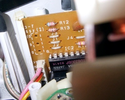
If you compare the previous blog image with this board, you'll notice that the jumpers J1 & J2 are bridged, whereas in the mile version they are not used.
I'll be testing this out when I run the mile unit up on the fuel injection rig, the easiest way is to spin up the sensor and see how far the tripmeter travels in say two minutes, bridge the J1 & J2 connections, reset the tripmeter and see if the distance is 1.6x greater for the same time & rotation speed.
Here's hoping it will, 'cos I've got an import too, that reads distances in kilometers, and although I can do the maths, it'll be good to see distance travelled match the road signs. for a change
Speedo fix after removing ABS ECU
Tue 14 Nov 2006
A few folks out there with a Yamaha GTS1000A have removed their ABS units, and then later discovered their speedometer does not work. Not surprising when the speedo gets it's info from the ABS ECU on these bikes, but there are genuine non ABS bikes out there too. So what was doing it.
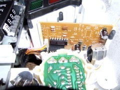
A little investigation in the wiring loom diagrams for both models suggests there is a difference at the speedometer area, so I removed the instrument cluster from a donor bike, a UK spec 4BH GTS1000A. Surprisingly, there was an undocumented sixway connector that interfaced with the speedo area, although on the ABS unit I was looking at, only four of the sixway connector pins were populated. This sixway connector fed the circuit board below, which I assumed processed the pulses to create a speedo reading.

This is the board that is different, as the speedo stepper motor only has three inputs, this board has four inputs potentially, and has several outputs. One to odometer, one to the trip meter via the black horizontal connector, and a pink output to the speedo from the white vertical element.The chip is a Toshiba TD6330BP, a generic stepper motor driver, with optional external divisor inputs and outputs, as well as Schmitt circuitry, which is useful for processing inductive pickups.
After looking at the circuit board and the fiveway white strain block, I noticed the middle pin was not used and noted there was Assy(1) and Assy(2) markings plus a lot of the board is not populated with electronic components. As the speedo only has and needs three inputs, a 12V feed, a 12V ground and a pink input from the board, and this leads to the white vertical element on the left of the board, which ony uses four out of five potential solder areas. The only available space for a potential signal ground from the front wheel sensor would bridge to the board ground. Reading the specs of the chip, the ground plane is well isolated, so I thought I would feed the missing part of the inductive signal pulse into this, with the existing yellow/red wire feed being the other.
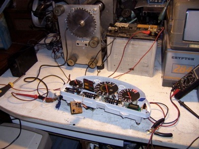
First of all, I needed to generate a pulse, fortunately I had a homemade variable speed fuel injection rig that had a single toothed wheel matched to a two wire inductive sensor, just like the Yamaha front wheel sensor...sure there wasn't a lot of teeth on it, but it would spin up to 11000 rpm, so I should get a signal. After hooking a 12V battery up to a charger...(don't you just love it when you want to do something and stupid things get in the way)...to create my power feeds, which incidentally are brown/black in large white connector block becomes +12V, black/brown in the blue connector is ground, and one feed from the inductive pickup is fixed to the yellow/red wire in the large white block , and the other makes contact with the black/brown in the blue plug.
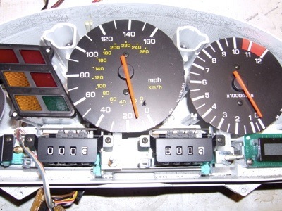
Switch on the motor and yippee it works. Switch it off and it stops!
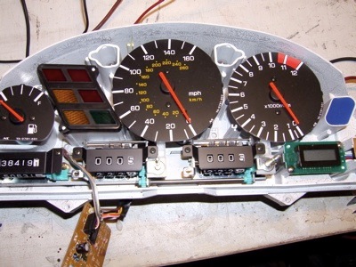
Notice how the odometer and trip meters have moved on.
So if you plan on getting rid of the ABS system on a Yamaha GTS1000A and want to get your speedo to work, you will need to jump the yellow/red wire in the ABS ECU plug to the white wire from the wheel speed sensor, and break into the loom to pick up the black/brown ground wire and splice the black wire from the front wheel sensor into it. Might be best to do this at the small white plug connector near the top of the left hand side Omega Chassis rail that connects the front wheel sensor into the main loom.
A little investigation in the wiring loom diagrams for both models suggests there is a difference at the speedometer area, so I removed the instrument cluster from a donor bike, a UK spec 4BH GTS1000A. Surprisingly, there was an undocumented sixway connector that interfaced with the speedo area, although on the ABS unit I was looking at, only four of the sixway connector pins were populated. This sixway connector fed the circuit board below, which I assumed processed the pulses to create a speedo reading.
This is the board that is different, as the speedo stepper motor only has three inputs, this board has four inputs potentially, and has several outputs. One to odometer, one to the trip meter via the black horizontal connector, and a pink output to the speedo from the white vertical element.The chip is a Toshiba TD6330BP, a generic stepper motor driver, with optional external divisor inputs and outputs, as well as Schmitt circuitry, which is useful for processing inductive pickups.
After looking at the circuit board and the fiveway white strain block, I noticed the middle pin was not used and noted there was Assy(1) and Assy(2) markings plus a lot of the board is not populated with electronic components. As the speedo only has and needs three inputs, a 12V feed, a 12V ground and a pink input from the board, and this leads to the white vertical element on the left of the board, which ony uses four out of five potential solder areas. The only available space for a potential signal ground from the front wheel sensor would bridge to the board ground. Reading the specs of the chip, the ground plane is well isolated, so I thought I would feed the missing part of the inductive signal pulse into this, with the existing yellow/red wire feed being the other.
First of all, I needed to generate a pulse, fortunately I had a homemade variable speed fuel injection rig that had a single toothed wheel matched to a two wire inductive sensor, just like the Yamaha front wheel sensor...sure there wasn't a lot of teeth on it, but it would spin up to 11000 rpm, so I should get a signal. After hooking a 12V battery up to a charger...(don't you just love it when you want to do something and stupid things get in the way)...to create my power feeds, which incidentally are brown/black in large white connector block becomes +12V, black/brown in the blue connector is ground, and one feed from the inductive pickup is fixed to the yellow/red wire in the large white block , and the other makes contact with the black/brown in the blue plug.
Switch on the motor and yippee it works. Switch it off and it stops!
Notice how the odometer and trip meters have moved on.
So if you plan on getting rid of the ABS system on a Yamaha GTS1000A and want to get your speedo to work, you will need to jump the yellow/red wire in the ABS ECU plug to the white wire from the wheel speed sensor, and break into the loom to pick up the black/brown ground wire and splice the black wire from the front wheel sensor into it. Might be best to do this at the small white plug connector near the top of the left hand side Omega Chassis rail that connects the front wheel sensor into the main loom.
