Panhard Cylinder Liner Rebore Update 5
27/10/12 18:47 Filed in: Panhard Piston | Whatton
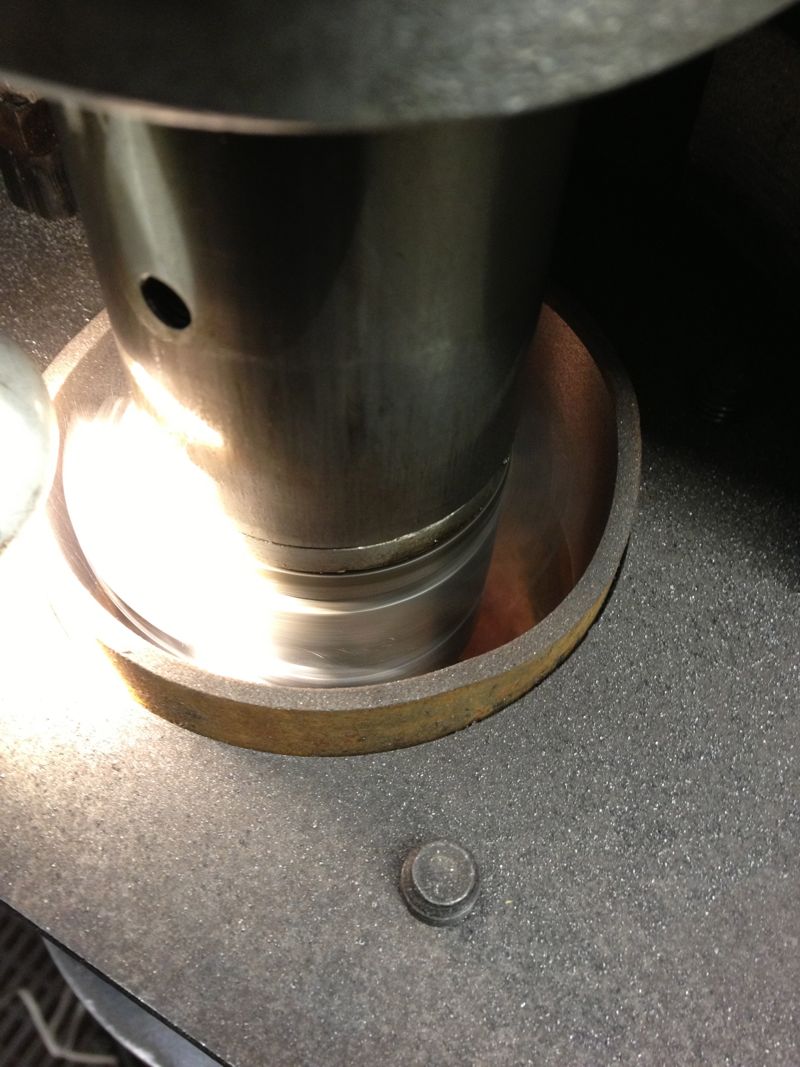
Using the freshly extracted & cooled cylinder liners from today, I loaded one into the Whatton boring machine jig, and started to centralise the Whatton to the liner. I usually drop the bar into the liner, centralise the machine using the three point cats paws, and tighten the base onto the mill bed.
I decided on an arbitrary test bore of 3.353” for the first cut, which is approximately 85.1mm, and just a bit oversize on the original liners.
I then started to machine the liner, but I noticed that the cut was greater on one side and not removing material from the opposite side, so I decided to recenter the Whatton at the top of the liner held in the rig. This is actually the bottom of the liner in reality...
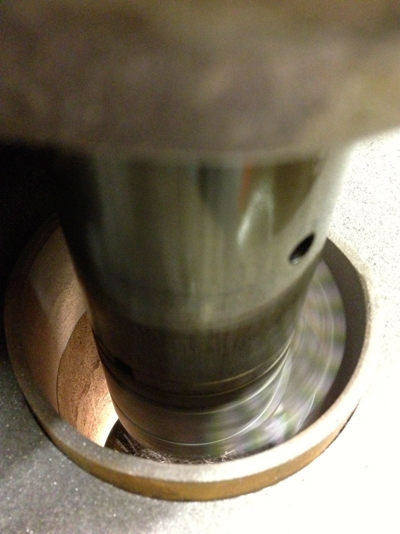
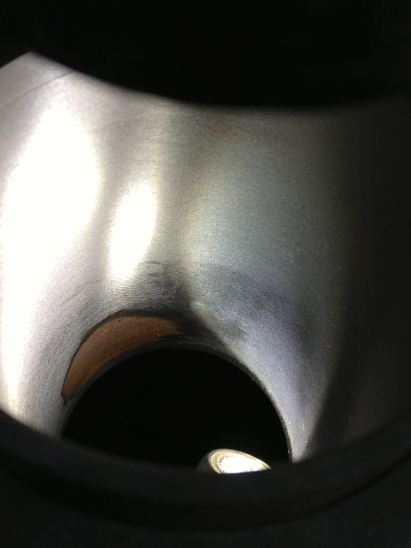
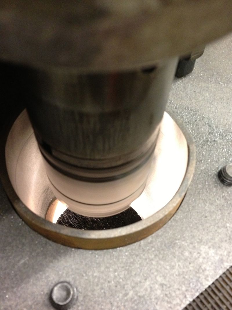
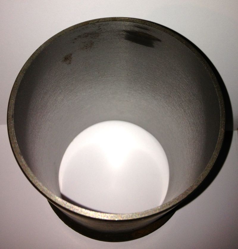
You can see the slight ring at the top in this picture above, when I centred the liner at the top of rig, and in the picture below, the area missed in the machining.
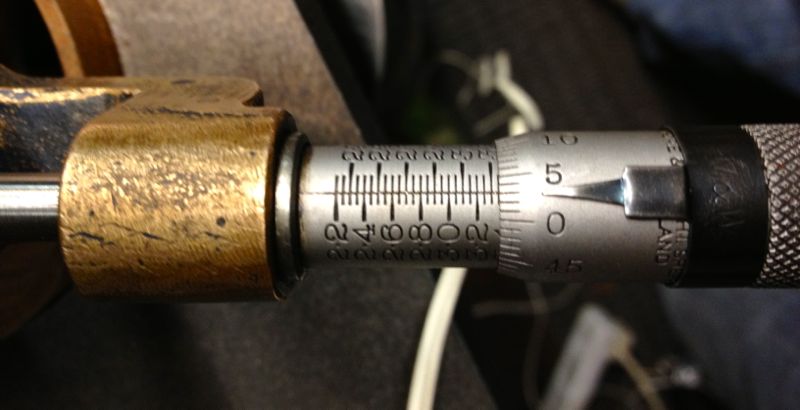
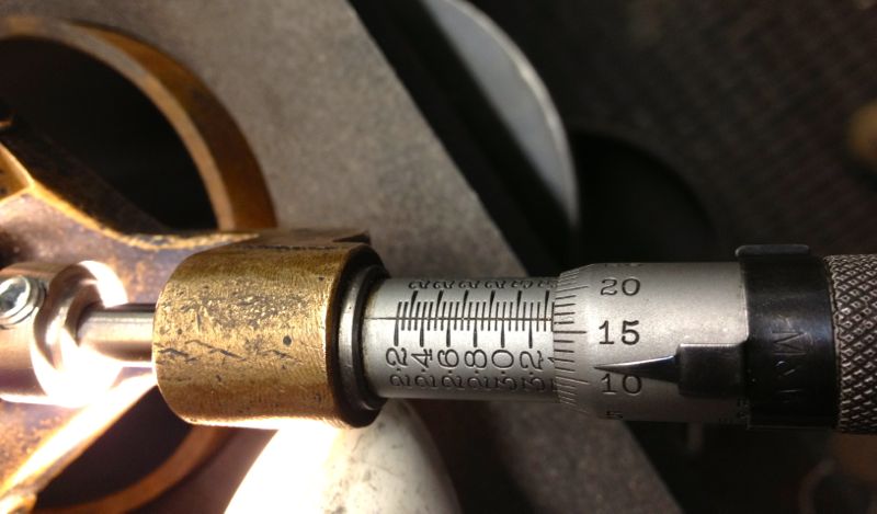
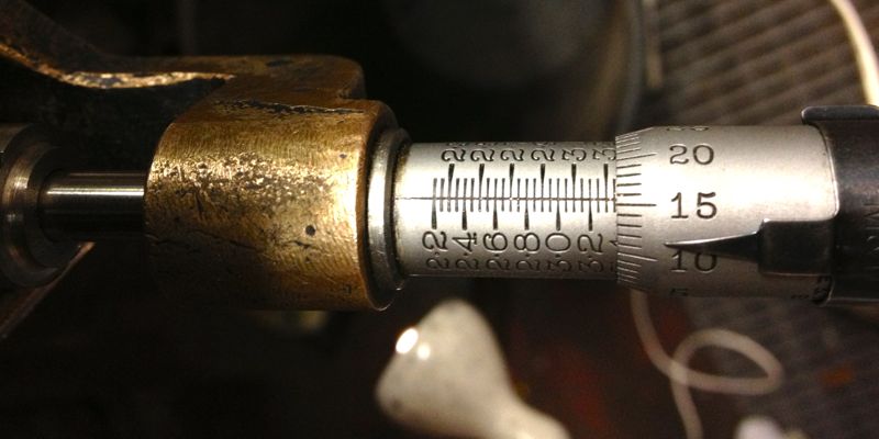
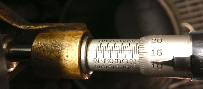
Obviously, further machining is required, but whether it will remove this blemish inside the liner is not known until you try, so it’s time to reset the cutting tip and see if cutting a slightly larger diameter will do it. New diameter is set at 3.3665”, as shown below, by sliding the tooltip out towards the micrometer.
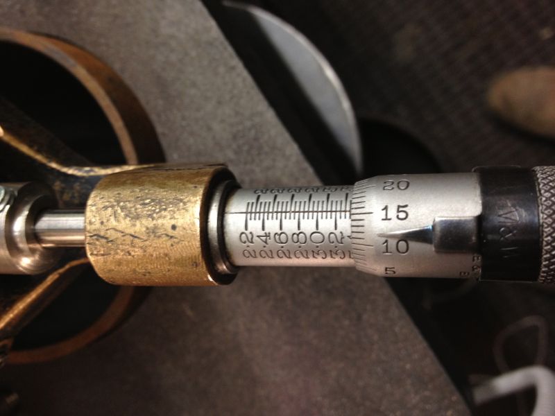
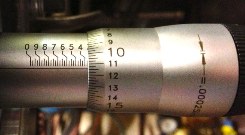
and then after tightening the tooltip locking screw, a quick recheck, but there’s not much difference here, about a thou, so it’s now reading 3.3655” as shown below.
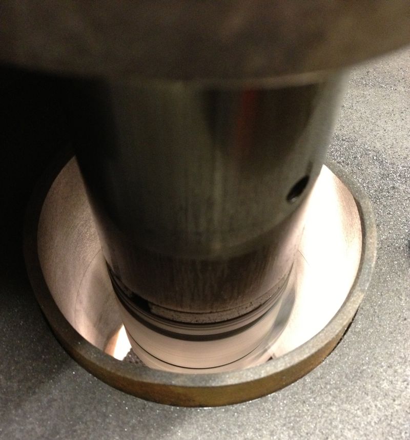
Notice how the top step is taken out by machining a larger diameter, but what will happen later on?
So when the second cut is finished, I let the tooltip pass through the liner & bottom mounting plate, and recheck the tooltip bore diameter, which hasn’t changed and reads 3.3655”. All is looking good.
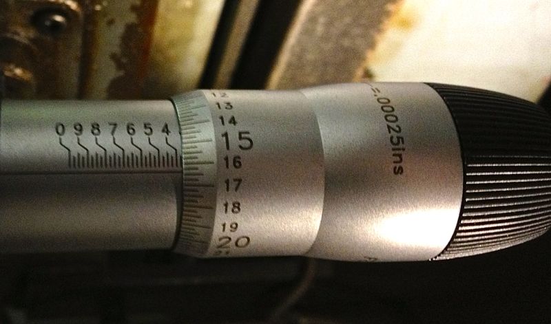
However a quick check with the Bowers imperial three point micrometer reveals the actual bore measurement is 3.3614”, so the Whatton is reading about 0.004” oversize.
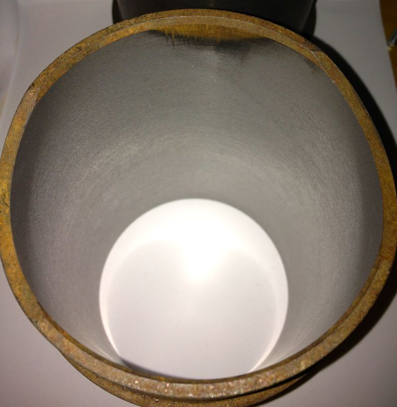
It’s still a good result, as I can now calibrate the Whatton micrometer to the actual bore size by resetting the detent. Incidentally the wear wasn’t quite machined out of the bottom part of the liner, (top in the picture below), but as it was less than 0.0005” on diameter when measured, the final cross hatch & prior honing process will remove this comfortably.
I decided to test the calibration by machining the other liner, but this time centre the Whatton with the bottom of the rig, as I originally started to do with the above liner. This left a very slight un-machined area at the top of the liner, which is really the bottom. No rings operate in this area, so it’s not critical, but either way it will be removed by the final honing process too.
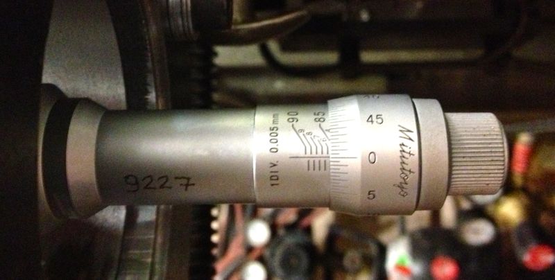
This second liner was machined at just under 3.366” using the Whatton direct reading micrometer, but after boring it measured 85.500mm with the three point Mitutoyo, and 3.3663” using the Bowers, so it’s well within my operating parameters.
A good days work, next up, reinstall the liners, and check the finished diameters, so the true clearance can be established or continue to test hone the cylinder liners using the Delapena hone. For the latter, I will have to CAD up a drawing, as I need to make a rig to hold the liners, before I can hone them properly. It’s not worth using the Whatton set up, as it’ll be too much disruption.
I decided on an arbitrary test bore of 3.353” for the first cut, which is approximately 85.1mm, and just a bit oversize on the original liners.
I then started to machine the liner, but I noticed that the cut was greater on one side and not removing material from the opposite side, so I decided to recenter the Whatton at the top of the liner held in the rig. This is actually the bottom of the liner in reality...
You can see the slight ring at the top in this picture above, when I centred the liner at the top of rig, and in the picture below, the area missed in the machining.
Obviously, further machining is required, but whether it will remove this blemish inside the liner is not known until you try, so it’s time to reset the cutting tip and see if cutting a slightly larger diameter will do it. New diameter is set at 3.3665”, as shown below, by sliding the tooltip out towards the micrometer.
and then after tightening the tooltip locking screw, a quick recheck, but there’s not much difference here, about a thou, so it’s now reading 3.3655” as shown below.
Notice how the top step is taken out by machining a larger diameter, but what will happen later on?
So when the second cut is finished, I let the tooltip pass through the liner & bottom mounting plate, and recheck the tooltip bore diameter, which hasn’t changed and reads 3.3655”. All is looking good.
However a quick check with the Bowers imperial three point micrometer reveals the actual bore measurement is 3.3614”, so the Whatton is reading about 0.004” oversize.
It’s still a good result, as I can now calibrate the Whatton micrometer to the actual bore size by resetting the detent. Incidentally the wear wasn’t quite machined out of the bottom part of the liner, (top in the picture below), but as it was less than 0.0005” on diameter when measured, the final cross hatch & prior honing process will remove this comfortably.
I decided to test the calibration by machining the other liner, but this time centre the Whatton with the bottom of the rig, as I originally started to do with the above liner. This left a very slight un-machined area at the top of the liner, which is really the bottom. No rings operate in this area, so it’s not critical, but either way it will be removed by the final honing process too.
This second liner was machined at just under 3.366” using the Whatton direct reading micrometer, but after boring it measured 85.500mm with the three point Mitutoyo, and 3.3663” using the Bowers, so it’s well within my operating parameters.
A good days work, next up, reinstall the liners, and check the finished diameters, so the true clearance can be established or continue to test hone the cylinder liners using the Delapena hone. For the latter, I will have to CAD up a drawing, as I need to make a rig to hold the liners, before I can hone them properly. It’s not worth using the Whatton set up, as it’ll be too much disruption.
blog comments powered by Disqus
