Panhard oil pump output
Sunday 04 March 2012 Filed in: Panhard Oil
I have mentioned earlier that the Panhard oil supply was designed to be a low flow, low oil pressure system, but I haven’t really explained why.
Originally the engine had a lot of roller bearings inside it, and crucially the crankshaft was suspended using these. In fact cylindrical roller bearing set ups are making a come back in engine design, especially in the USA where Timken are applying this to some current engines, to showcase the technology again, and also promote their own bearing interests. One of the reasons they are using it, is to reduce pumping losses, and the frictional drag reductions against the more common plain bearing engines, because there is an environmental need to make combustion engines more economical.
The Panhard engine was quite clever in that it used a small pump to get the oil roughly where it was needed, and then the centrifugal effect of the slingers in the crankshaft webs gave a speed related response to the engine needs. This was a good fit with the requirements of the engine, and although there was a maintenance issue with slingers clogging up, mileages were not great in the late 1940’s when the engine was being designed, and a 30,000 mile target wasn’t unreasonable. Fast forward to the 21st Century and maybe some things would be different now, and if you look at the evolution of a similar engine, the BMW R50 motorcycle, that moved from centrifugal oil supply to a cross drilled crank, and the more common one piece crankshaft & split connecting rods with plain bearings.
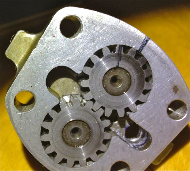
Aside from the maintenance issue with the slingers, there is nothing really wrong with the original oil pump, but if you read the history books you might be lead to believe otherwise. Here is the pump, and it is a gear type oil pump, which was a current design around the time, and it is more than adequate for the job. There are a couple of issues, that if it was being made today, that you would change, but I’ll elaborate later.The first one is, there are no rounded edges from the oil pump body into the output drilling, which is 90 degrees to it, and this will cause back pressure and cavitation, at higher oil volumes .
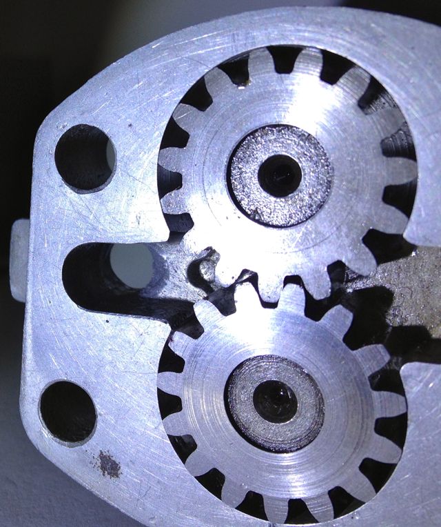
So if I was going to do one thing to address this, it would involve using a Dremel and doing this.
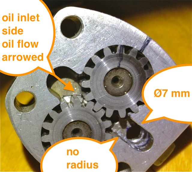
This modified oil pump will now flow more oil at speed, when you want it and there will be less bubbles in the oil as a result, which has the effect of improving the oil quality. I have successfully done this on three engines to date, and did test it out on the oil filter crankcase test rig many years ago. It is beneficial, and is one way of simply boosting the nett oil flow, but there is a bigger win win at the crankcase entry. If you were trying to maximise flow, you wouldn’t squeeze a garden hose pipe, but that’s exactly what Panhard did, because the crankcase oil inlet from the pump is 4.8mm diameter, yet the pump output is 7mm in diameter, which is almost a 50% reduction in cross sectional area. So after radiussing the outlet of the pump body there is an even bigger restriction downstream, and all the oil for the engine is fed by this small hole. It really doesn’t make sense with hindsight
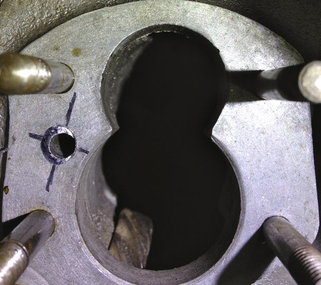
You can see the small inlet pipe into the crankcase, and also see where the oil pump mates up to it, which is the black circle I have inked in and the centre of the outlet is represented by the black lines. So again the flexible shaft is used to reshape this area, and the important thing is to match the mating diameters more closely. It makes sense to machine and open up this drilling to match the oil pump, as this will increase the flow rate into the main oil galleries, and it has no effect on the pressure of the system, contrary to what you might think. The pressure in the unmodified camshaft is controlled by the cross drilling after this, and the cylinder head feeds likewise by the size of their respective openings too.
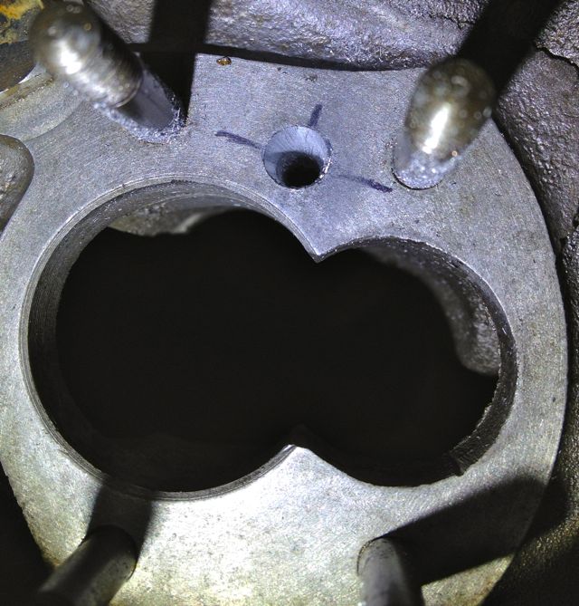
Crankcase main oil gallery modified to match oil pump outlet diameter.
Originally the engine had a lot of roller bearings inside it, and crucially the crankshaft was suspended using these. In fact cylindrical roller bearing set ups are making a come back in engine design, especially in the USA where Timken are applying this to some current engines, to showcase the technology again, and also promote their own bearing interests. One of the reasons they are using it, is to reduce pumping losses, and the frictional drag reductions against the more common plain bearing engines, because there is an environmental need to make combustion engines more economical.
The Panhard engine was quite clever in that it used a small pump to get the oil roughly where it was needed, and then the centrifugal effect of the slingers in the crankshaft webs gave a speed related response to the engine needs. This was a good fit with the requirements of the engine, and although there was a maintenance issue with slingers clogging up, mileages were not great in the late 1940’s when the engine was being designed, and a 30,000 mile target wasn’t unreasonable. Fast forward to the 21st Century and maybe some things would be different now, and if you look at the evolution of a similar engine, the BMW R50 motorcycle, that moved from centrifugal oil supply to a cross drilled crank, and the more common one piece crankshaft & split connecting rods with plain bearings.
Aside from the maintenance issue with the slingers, there is nothing really wrong with the original oil pump, but if you read the history books you might be lead to believe otherwise. Here is the pump, and it is a gear type oil pump, which was a current design around the time, and it is more than adequate for the job. There are a couple of issues, that if it was being made today, that you would change, but I’ll elaborate later.The first one is, there are no rounded edges from the oil pump body into the output drilling, which is 90 degrees to it, and this will cause back pressure and cavitation, at higher oil volumes .
So if I was going to do one thing to address this, it would involve using a Dremel and doing this.
This modified oil pump will now flow more oil at speed, when you want it and there will be less bubbles in the oil as a result, which has the effect of improving the oil quality. I have successfully done this on three engines to date, and did test it out on the oil filter crankcase test rig many years ago. It is beneficial, and is one way of simply boosting the nett oil flow, but there is a bigger win win at the crankcase entry. If you were trying to maximise flow, you wouldn’t squeeze a garden hose pipe, but that’s exactly what Panhard did, because the crankcase oil inlet from the pump is 4.8mm diameter, yet the pump output is 7mm in diameter, which is almost a 50% reduction in cross sectional area. So after radiussing the outlet of the pump body there is an even bigger restriction downstream, and all the oil for the engine is fed by this small hole. It really doesn’t make sense with hindsight
You can see the small inlet pipe into the crankcase, and also see where the oil pump mates up to it, which is the black circle I have inked in and the centre of the outlet is represented by the black lines. So again the flexible shaft is used to reshape this area, and the important thing is to match the mating diameters more closely. It makes sense to machine and open up this drilling to match the oil pump, as this will increase the flow rate into the main oil galleries, and it has no effect on the pressure of the system, contrary to what you might think. The pressure in the unmodified camshaft is controlled by the cross drilling after this, and the cylinder head feeds likewise by the size of their respective openings too.
Crankcase main oil gallery modified to match oil pump outlet diameter.
blog comments powered by Disqus
